As I’ve mentioned before I’m currently campaigning to reconquer the 3d modeling superpowers I once possessed in my youth but lost to the inevitable betrayal of proprietary software — looking at you AutoDesk!
And it is going well.
In the early 1990s, I could create a clean 3d model of something as fast as an expert machinist could measure an artifact and dictate to me its geometry. Today, I feel like I can create a pretty clean 3d model of any such engineered item. I still don’t have nearly the full speed I once did and while that can be frustrating for me, I’m now past the point where Blender seems like a completely foreign language. I’m fast enough for practical projects and getting faster every day.
At this point some of the problem is that Blender is not 1980s AutoCAD. I’ve come to now better appreciate some ancient AutoCAD features. AutoCAD took some things more seriously than Blender: accuracy, freedom units (if not true freedom), comprehensible polar arrays, mathematically clean circles, snapping to circle parts (tangent, quadrants, centers), intersections, simple measurements, simple non-manifold lines, lining things up, trimming things down, and Lisp.
That last one is kind of trippy, right? Lisp? John Walker, the main creator of AutoCAD defends that choice on his website. Obviously I am a fan of the thinking behind Lisp but I want to highlight this part of Walker’s justification which I hope you will be reminded of when this post devolves into esoteric Blender topics.
Because Autodesk’s implementation of Lisp is completely interactive and provides on-line debugging facilities, Lisp is among the easiest of languages to master. Because the response to all changes is immediate, programs may be tested as easily as with an interactive BASIC interpreter.
Note that facilitating interactive programming was also the main reason Hewlett Packard chose Lisp for their calculators. My language has the same rationale.
So that’s state of the art of weird interactive programming idioms in 1985. What are the weird interactive programming idioms of today?
While I’ve been putting my energy primarily into recovering my technical modeling skills, in the Blender world the kids these days have moved on to something more exciting. I’ve been trying to get high fidelity accurate geometry, but for most Blender users (usually correctly referred to as Blender artists) the emphasis is heavily on how things look. This is why until now I’ve largely ignored very important Blender topics like texturing, UV mapping, lighting, compositing, and rendering and presentation in general. But as I have started to explore these topics, I’ve found something quite extraordinary: a way of programming computers that was completely unknown to me.
If you fully explored our recent Vanitas project, you may have come across this jumbled riot of technical looking stuff.
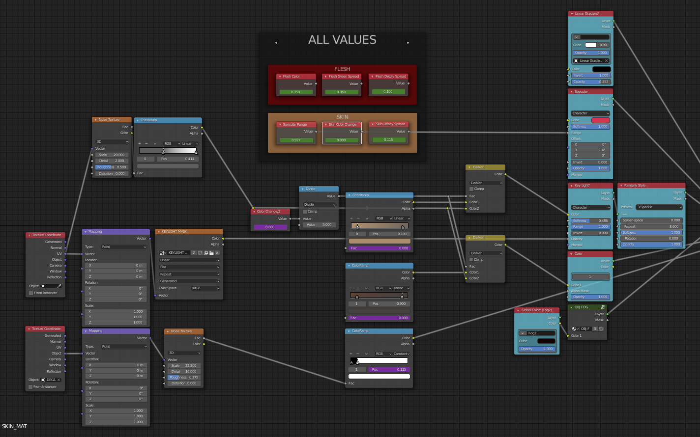
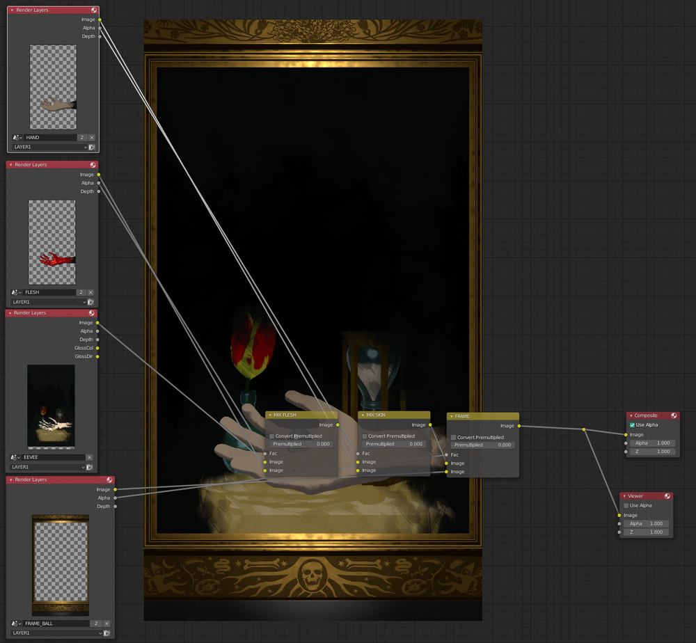
You would be forgiven for taking it from a distance and thinking, "Must be some idiosyncratic Blender arcana; wow those guys are really into some complicated freaky stuff." That’s kind of what I thought at first. But there’s something much more serious and interesting going on here.
I don’t really know the correct official name for this kind of software development if there even is one. This is Blender’s "Node Editor". I’m hesitant to use the phrase "node programming" (because of a recent web browser fad); so let’s think of it as graph (theory) programming.
I have noticed Blender rapidly expanding their "node" system in recent releases. In 2.93.1 I now see the following: Shader Editor ("Shader nodes"), Geometry Node Editor ("Geometry nodes"), and Texture Node Editor ("Texture nodes"). I added the tool tip text to show that it’s weird and inconsistent that the Shader editor is not called the "Shader Node Editor" — this is typical of the current active development of these systems.
What exactly is this? Well, obviously Blender, a state of the art computer graphics program, has some pretty competent ways to deal with computer graphics. What’s interesting is that has slowly over the course of its evolution been churned back into the program’s interface. Let me give you a quick example. Let’s say I want to move an object in 3d space on the X axis by 2 units. I would type "gx2" (details unimportant). Now imagine you are using Blender’s completely different feature of video editing and you want to move a track 2 frames later in the sequence — you type "gx2". That’s a simple tiny example but the way you handle and work with 3d geometry is also the way you do everything in Blender. That alone is a very powerful idea.
I could be wrong but my guess is that it started as a misguided attempt to make "real" programming "easy". By adding an utterly gratuitous superficial graphical aspect to a process that absolutely does not need it, everything is much easier, right? Well, that’s the thinking in Silicon Valley. But this is not simply pointless GUI dreck. It is taken for granted that the people who would use these graphical elements in Blender would be pretty competent with at least one sophisticated graphics editor.
But once you realize that moving video tracks around and manipulating other UI elements as geometric objects should be trivial for people who can model complex 3d geometry, things get interesting. If the barrier to entry was formerly having to learn some complicated graphical editor and now that is a non-issue, what else can you do with that?
Fundamentally this graph theory programming style is no different than any code. Each node is a function. Each edge (the connecting lines - adorably and accurately called "noodles") is like a function call. This allows Blender developers to very cleanly compartmentalize their work and focus on small tools doing one simple thing well.
Where else have we heard that philosophy? It is, in fact, a cornerstone of Unix.
And I am in fact struck by the parallels between node editing in Blender and unix plumbing with pipes and redirection. A unix pipe is a way to take the output of one small specialized block of code and feed it into the input of another one. This is exactly how Blender nodes work. It’s a shame more Blender people don’t use Linux/OSX/unix because they’re already experts at one of the most important features.
That’s cool. But it goes deeper than rediscovering a feature of 1970s computing. In unix you can get complicated, but the original concept had its complexity capped for practical purposes at simply having a lot of nodes. In other words unix complexity means a command line with a dozen small programs strung together with pipes. But crucially each program generally can take one input and produce one output — the standard input and output. Blender’s interface can easily shrug off that limitation.
Like unix pipes, Blender nodes can take or produce a fire hose of data on its internodal plumbing. Unix moves and processes lines of text. Blender does… uh… other stuff. I guess pixels (or subpixels) mainly. It’s complicated. But trust me when I say that it’s eerily similar. Blender nodes can follow the unix model of using robust simple small subunits that can be arranged into baroque but highly reliable systems of insane complexity. Blender nodes go on to improve on that power by easily organizing many possible input streams and output streams per node.
What good is this? I think we’re just starting to find out. Obviously if Blender users ever decided they needed the functionality of Make, they’d be able to construct baroque DAGs far easier than the current crusty Makefile. I have a feeling that Blender style node editing might be very useful for enhancing parallelism - a notoriously hard thing to get computers to do well. Blender’s current marquee node feature is as good of an example as any. Here’s an image from a video by Default Cube (aka CGMatter).
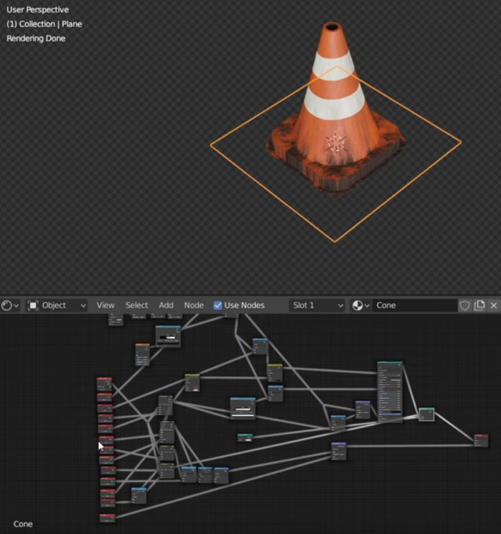
Here he is "writing software" by using Blender’s shader editor. What does this software do? Well, that orange square is a geometry primitive, a "plane" or quad or, deep down, two right triangles stuck together into a square if you like. And that’s all the geometry he uses. And yet there’s a traffic cone there. Is it a photo? What is that? How did that get there? It turns out that cone was created whole cloth from nothing using only the shader nodes shown.
As with proper software, the red nodes on the left have been organized into what we unix people call arguments or options. He can adjust values in those nodes and change things like how tall the cone is, how big the base is, the stripe placement, and, because he’s a master, how dirty the thing is! Pretty cool, right?
You can imagine that if a scene had a million cones that used this system, a computer could methodically divide up the work among its computing cores instead of choking on the fine geometry of a million finely modeled props loaded into memory at once. It’s not a panacea to be sure, but its an interesting option. Pretty cool indeed.
I feel this Blender node style of programming does have some limitations. It seems that indiscriminate looping might be more tricky and I can’t envision recursion at all. But not to worry! There is another ace card to be played. Now that I’ve brought you up to speed on the latest and greatest in interesting software development, at least in the world of Blender artists, let me show you the next level!
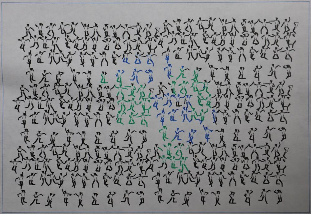
While I have been studying these topics of procedural texturing and other programmatic graphics techniques I’ve been reminded of some of my work in the early 1990s. Specifically an AutoLisp program I wrote back then to create these little dancing stick people. (Note this was inked with a pen by an ancient HP pen plotter!)
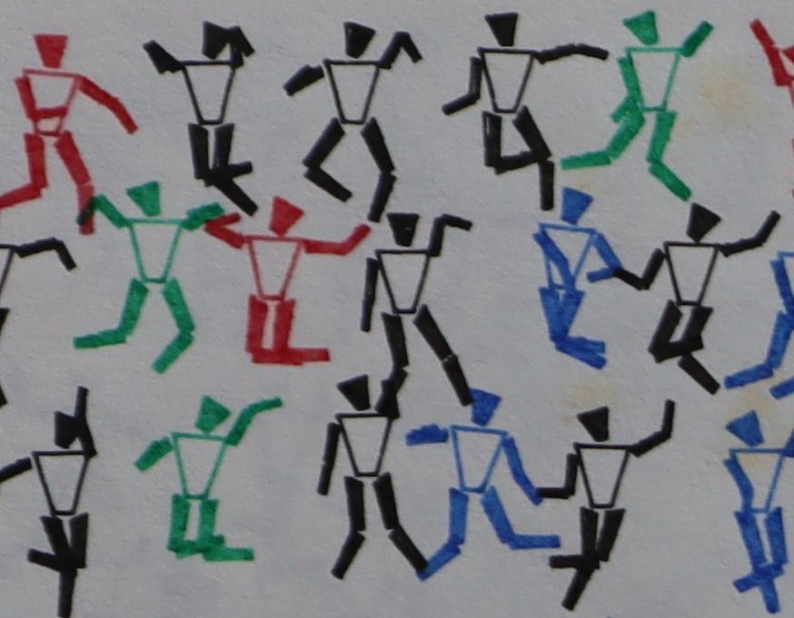
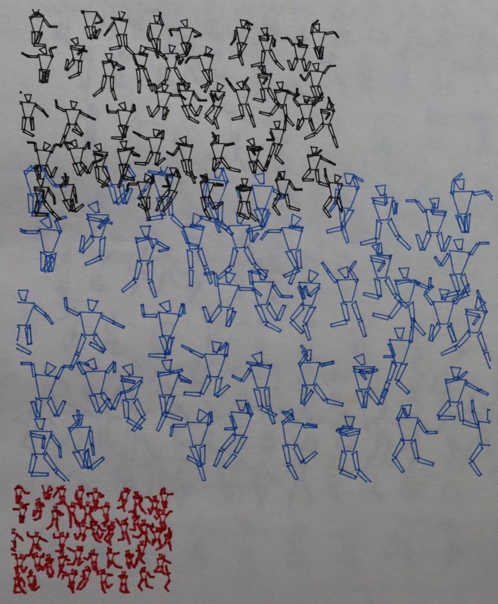
This one you can see I started laying out the little guys on a earth-like shape with green continents and blue wate, etc. I’m not sure I ever quite got what I was hoping for, but it shows I was thinking about applying interesting programmatic patterns to things even back then.
Today in the Blender world, covering goemetric shapes with fancy pixels is called texturing. I wondered if it was possible to use texture nodes to accomplish this. And I’m sure it is — Default Cube could do it I’m sure. But I can’t. The reason is that I actually am much better at old school programming. And Blender doesn’t disappoint! Blender has a texture node called simply "Script" which allows you to import your own code right out of Vim and into the node graph. Let’s do this!
After a marathon of video tutorials (thanks Default Cube!) and reading the Open Shading Language specification cover to cover, I was able to produce this.
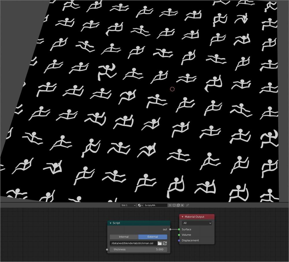
This is all procedural and when I hook it up to the current frame number, I can animate it. Note that they are all subtly different.
This is actually a texture and can be "applied" to any object, even preserving the animated quality. I could keep working on this and make it "better" but really, I just wanted to prove the functionality to myself and learn how this stuff works. I feel I’ve done that.
What else can this kind of technique be useful for? I think the sky is the limit. Here are some random applications I’ve thought of:
-
Greebles (the special effects term for random spaceship parts).
-
Procedural grass and plants.
-
Procedural props that get replicated a lot (like the cone).
-
Something like a coral reef where stuff moves back and forth.
-
Placing rocks and geology.
-
Carving rivers sensibly.
-
Condensation or drops of sweat on a face.
-
Some kind of futuristic cyber implant display in the skin.
-
A pit of writhing snakes like in Indiana Jones.
-
Ant trails composed of simple lines but rendering with armies of marching ants.
-
Centipede legs - can be as long as you like.
-
Dirt or damage effects based on proximity to something, e.g. an explosion.
Really, this is pretty powerful. But I hope I’ve impressed upon you that unix is powerful and this interactive node editor stuff is kind of like next level unix thinking. Will we see node based graphical software development come to mainstream software engineering? It’s such a strong idea, that I somewhat doubt it. But like the gamers, the Blender kids will keep pushing the frontiers of computer science even when computer science fails to notice.
Appendix
For completeness I’ll include the code for this if anyone is interested. Note that the syntax highlighting is courtesy of C — demonstrating that learning C still has benefits!
// stickman.osl - Chris X Edwards - 2021-08-07
// P is a preset global variable which seems similar to a Texture
// Coordinate Node's Object property. Also u and v are present. See spec p45.

// == Functions ==
int circle(point V, point C, float r){ return (distance(C,V) < r); }

int line(point V, point E1, point E2, float w) { return (distance(E1,E2,V) < (w/2)); }

// == Main Shader ==
shader stickfigure (
  float thickness=2,           // Default thickness.
  int current_frame=1,         // Passed from #frame property of attribute node.
  output float out = 0
)
{ // === Shader Body ===
out= 0; // Default to black. All true checks can turn on value.
float T= thickness * .01;
point LP= P; // This will be a Localized point.
LP.x= P.x-floor(P.x)-.5;
LP.y= P.y-floor(P.y)-.5;

// Body Point Definitions
float legL= .25;
float shnL= .20;
float armL= .18;
float wriL= .16;
point head= {0,.15,0};     // Head center.
point neck= {0,.15,0};     // Neck.
point shld= {0,.04,0};     // Shoulder.
point hips= {0,-.15,0};    // Hips.

// Master angle. Randomness starts here. Unsigned Perlin noise.
float A= current_frame * (M_PI/100) + noise("uperlin",P);

// Knee positions
point kner= rotate( hips+point(0,legL,0), M_PI+A/2, hips, hips+point(0,0,1) );
point knel= rotate( hips+point(0,legL,0), M_PI-A/2, hips, hips+point(0,0,1) );
// Feet positions
point fotr= rotate( kner+point(0,shnL,0), M_PI-A*3.5, kner, kner+point(0,0,1) );
point fotl= rotate( knel+point(0,shnL,0), M_PI+A*3.5, knel, knel+point(0,0,1) );
// Elbow positions
point elbr= rotate( shld+point(0,armL,0), A, shld, shld+point(0,0,1) );
point elbl= rotate( shld+point(0,armL,0), -A, shld, shld+point(0,0,1) );
// Hand positions
point hndr= rotate( elbr+point(0,wriL,0), A+.8, elbr, elbr+point(0,0,1) );
point hndl= rotate( elbl+point(0,wriL,0), -A+.8, elbl, elbl+point(0,0,1) );

if (circle(LP,head,.07)) { out= 1; }
else if (line(LP,neck,hips,T)) { out= 1; }
else if (line(LP,hips,knel,T)) { out= 1; }
else if (line(LP,hips,kner,T)) { out= 1; }
else if (line(LP,shld,elbr,T)) { out= 1; }
else if (line(LP,elbr,hndr,T)) { out= 1; }
else if (line(LP,shld,elbl,T)) { out= 1; }
else if (line(LP,elbl,hndl,T)) { out= 1; }
else if (line(LP,kner,fotr,T)) { out= 1; }
else if (line(LP,knel,fotl,T)) { out= 1; }

} // === End Shader Body ===
Update 2021-09-07 -
I was just reminded of another example of this kind of graphical programming. The photogrammetry program Meshroom uses this kind of node editing approach in a way that formerly would/should have been done with shell scripting. As a shell scripting expert, I don’t appreciate the overhead, but I do recognize that it’s easier for beginners and might allow for more complex data flows (though I don’t sense it is necessary in this application).
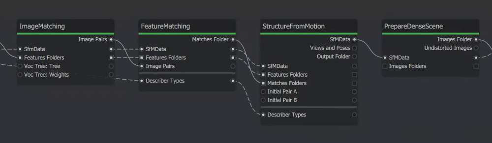
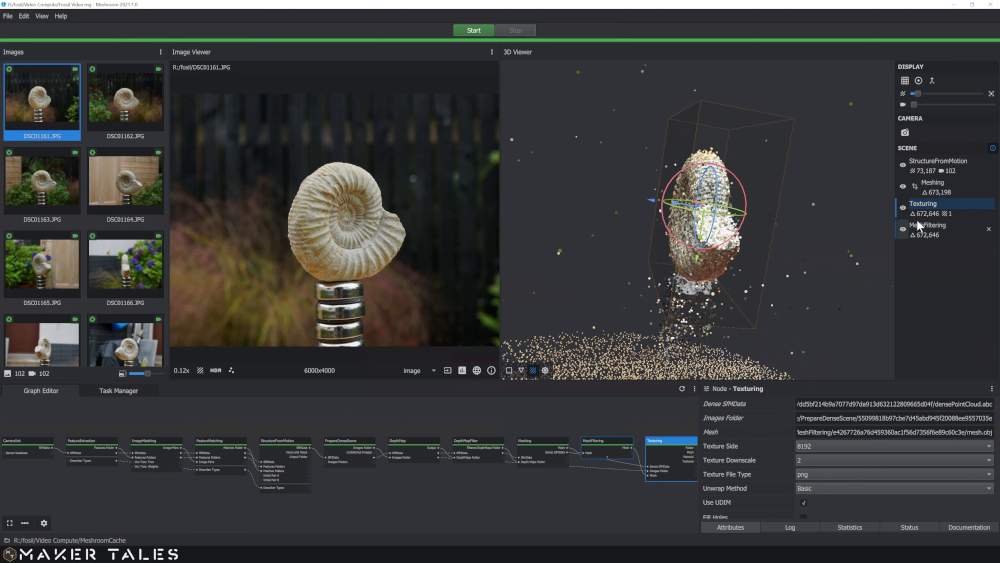
These images were taken from this very useful video explaining an entire photogrammetry pipeline using Meshroom.