Geometry Nodes For Regular Geometry
:date: 2024-12-22 16:40 :tags:
As I've written about before, I'm quite interested in node programming and in particular Blender's geometry nodes. I have been doing fancy things with geometry nodes for several years now, even professionally. I wanted to write about this topic to explain what it is all about and why I find it so interesting. Also I hope to share a genuinely useful technique I came up with for solving a very common real world modeling problem. Even if you're not in the graphics business, I hope you can at least get a sense for the kinds of heavy lifting that is done behind the scenes in modern video games, animated movies, visual effects, etc.
The Problem Of Complicated Graphics
Computer graphics are hard. Attending to enough light physics details to produce a convincing image requires an enormous amount of computation. AI training and bitcoin mining also require a lot computation and this is why those things are typically done on GPUs — the G stands for graphics, the original king of burning through computation. Having a special sub-computer — the GPU — just to calculate graphics is only one trick. The graphics business is filled with trickery!
To get a good look at the normal tricks used in computer graphics let's take a look at a very difficult programming challenge: making a AAA game in 1998. Here's a shot from the original hit game Half-Life.
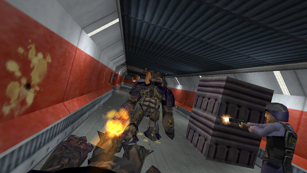
Ignore the characters and think about this environment. By my count the hallway has 10 rectangular surfaces or quads (which breaks down to 20 triangles). The crate has 4 or 5 quads. This means that (until the next hall) the entire foreground scenery is about 30 triangles. This extremely low polygon count is what allowed Valve to create a game where one could move through an environment rendered dozens of times per second. Obviously the big illusion here is that for each of those 15 quads they calculated the transformation of 15 rectangular bitmap images to provide the surface appearance. (Actually some are reused.) They distorted those images to fit the perspective and view and placed them that way onto the screen.
That was 1998. Back then, all of the actual fine surface geometry was completely absent (except maybe in the viewer's imagination). Note the regular pattern of slats on the crates, the ceiling, and the baseboards. There are also regular patterns in the hall section seams, the lights, and the floor tile. All of that is just colored in with texture images painted onto entirely flat geometry.
Modern games have tried to push the graphics quality by eliminating the visual problems caused by limited geometry. Today there are even fancier tricks. Check out this example of a very simple rectangle.
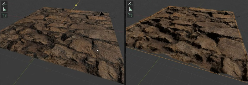
On the left it is painted with a complex texture as described. On the right, an additional calculation is done based on some precalculated map. This map could be a height map telling the height at each pixel (e.g. stones are high, the spaces between them low). It could be a normal map letting the rendering engine know what direction light should bounce off that particular pixel. There are many other maps that can impart impressive trickery to rendering pipelines (roughness, specular, gloss, metalness, opacity, emission, subsurface, bump, ambient occlusion, etc.). But all of that is just dressing up a single quad in ever more sophisticated ways.
Clearly the results can be quite impressive. But it turns out that there are some scenes where this kind of approach has some challenges. Consider trying to render computer models of the following scenes.



(That last one is actually computer generated by this game.)
It is true that you could go deep into the bag of mapping tricks and define an opacity/transparency map or use alpha channels that might be able to somewhat approximate this kind of thing. But the whole idea of this kind of scene is that there's an outside and an inside and that means the thickness of the wall boards can not be a convenient zero. In a scene like this that will be obvious, especially at shallow view angles. Here's what that looks like as seen in a 2003 game ( Prince Of Persia - Sands Of Time).
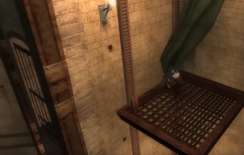
Note the very flat door bars on the left. Also note that to give the illusion of the thickness I'm talking about, they used two quads on the platform and painted them both with their flat texture. Note also that this scene is full of regularly spaced elements.
Is there a better way to achieve a higher quality realism other than to dress up a single plane with rendering tricks?
Yes there is! The answer in Blender is...
Geometry Nodes
Ok, so what are geometry nodes? Geometry nodes are a way to generate more geometry based on some kind of algorithm or recipe. This allows you to keep that simple single rectangle as the only geometry you need for the basic definition of a surface (e.g. the ceiling of the hallway) and if the finer geometry (e.g. the vent slats on the ceiling) can be defined with some kind of logical procedure, that finer geometry can be generated on-the-fly at rendering time. The advantage is that you get temporary real geometry that looks correct at any angle and scale — as many polygons as it may take.
Geometry nodes are actually a generalized Blender modifier — the most complex one. To understand this modifier idea let's first look at a very simple modifier. Consider a lathe. If you're going to be turning parts on a lathe, you don't have to really talk about all the resultant XYZ 3d geometry of your table leg or whatever. You can just define its 2d profile and say "and then we turn that on a lathe". That's obviously an enormous simplification in conveying that idea. Letting a computer take care of the details also tends to reduce errors as a bonus. It turns out that the Blender Screw Modifier does exactly this lathe kind of expansion of simpler geometry (i.e. the 2d profile to be turned into the full 3d object).
So that's a particular traditional modifier doing a particular comprehensible and sensible thing. Geometry nodes are like an omnipotent modifier that can do anything you can dream of that can be programmed — including re-implementing the screw modifier.
While geometry nodes can do pretty much anything (I believe they could literally model the physical tape of the Turing machine that demonstrates this), the reality of the situation is that there are some things that are easier to do than others. Here is a collection of very typical "Geometry Nodes How-To" video thumbnails I collected. Can you spot a theme?

As you can see, Blender artists are delighted to put geometry nodes to work creating random geometrical elements. For example if you have a field and there are rocks strewn around the field, where do you put those rocks? In the past the artist would have to manage the random placement explicitly. Today you can not only have Blender geometry nodes impartially fling the rocks into place, you can have the same system create the rocks from scratch!
To understand the emphasis on random geometry, consider one of the simplest geometry node setups possible. This demonstrates why so many applications of this tool look like this.
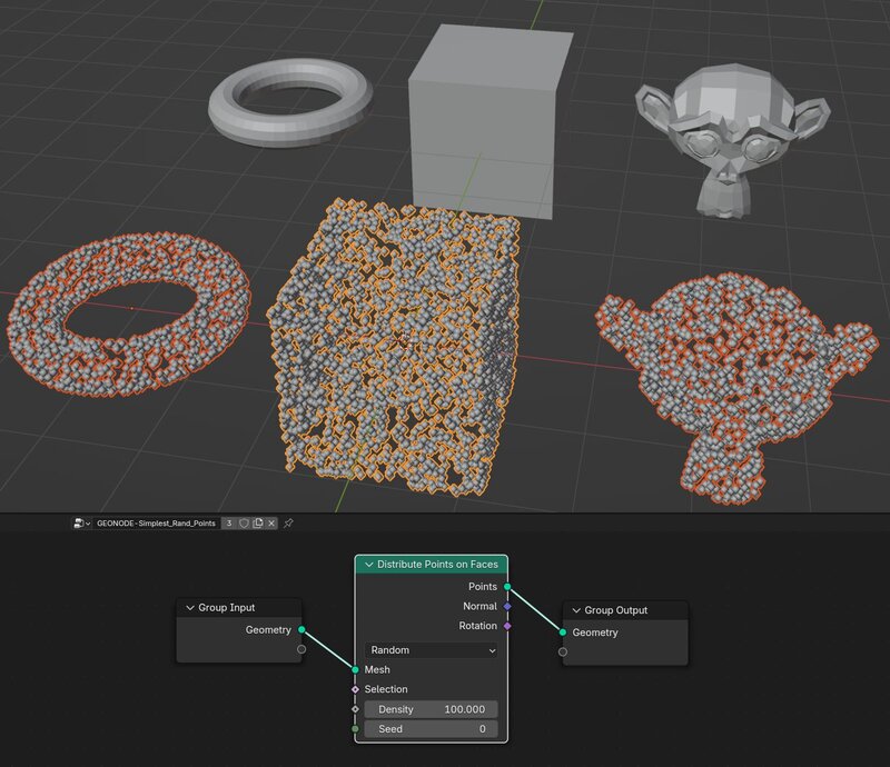
As you can see, implementing a random placement is pretty easy. I think it is actually easier than putting things in a non-random location — and that is what I usually need to do.
Non-Random Geometry Nodes
The ability to place random geometry is pretty cool and can certainly be helpful filling in naturalistic environmental details. However the scene I proposed modeling with the boards is not really random at all. A lot of my projects are architectural modeling and I find it requires a lot of non-random geometry. This is stuff that's easy to describe and hence suitable for geometry nodes, but just not random.
Take a look at some example use cases I found around my house.
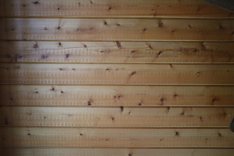
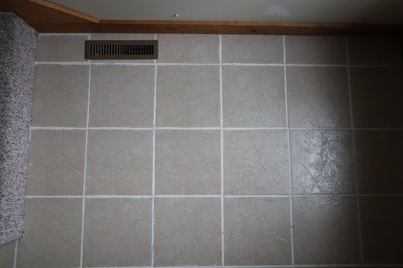
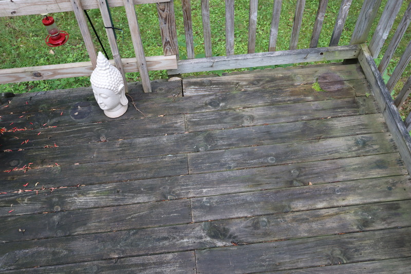
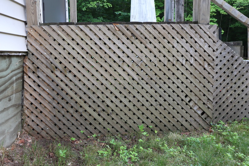
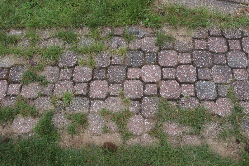
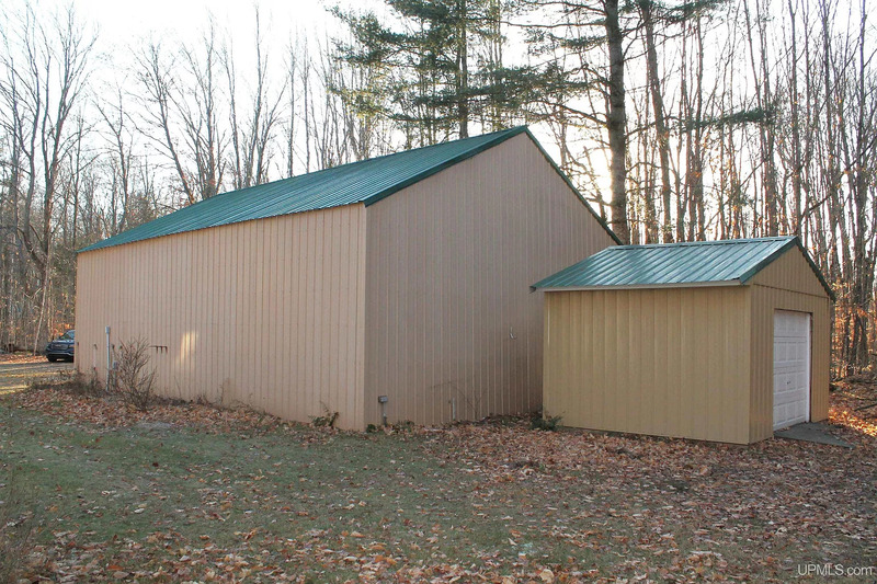
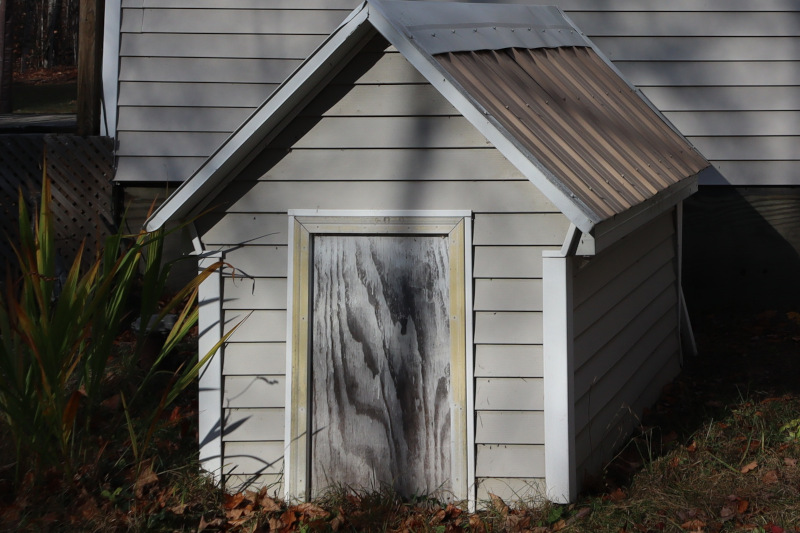
How To
Let's focus on that last one, the siding. Or course I could model a piece of siding and then use an array modifier to replicate it.
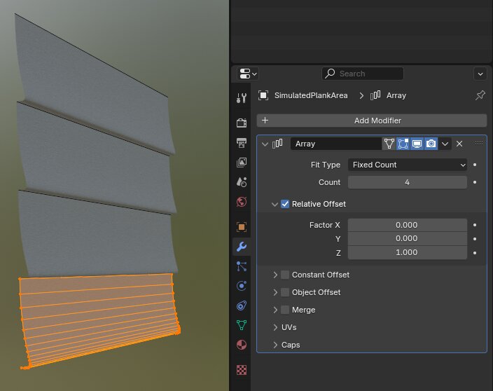
All done! Right? Well, unfortunately, no. The array modifier just puts multiple instances of the original in a regular rectangular pattern and that is not going to actually be useful when working on real projects where the complexity will be more challenging. For example what if we need this siding to be trimmed on an angle to fit under a roof? What if we need a door or a window or some other element that can not have siding?
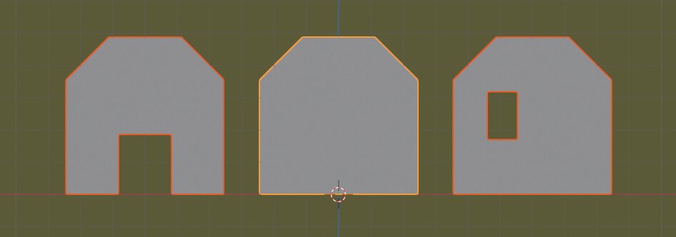
Basically this siding needs to be trimmed to fit in a somewhat similar way that a contractor would install it. Now you can see how things can get very messy very quickly. And it's no good just modeling all the siding pieces by trimming the geometry using Blender's normal editing tools. First off that would blow up the polygon count in the basic model. But there's a worse problem. Imagine you model a 5" piece of siding and then laboriously go around every window and door and nicely trim it to fit. Not super easy but it's doable. But then you realize you really want 8" siding or siding with a slightly different profile or vertical siding, etc. Now you can appreciate how having a programmatic way to fill in the siding to cover an arbitrary surface is so valuable.
There are essentially two major problems that need to be solved. First, you want the siding trimmed neatly to any irregular perimeter shape, and second, you want it to be removed from any window or other insular penetration. At first I thought these were basically the same problem — trim to the right shape — but no, Blender is a bit fussy about faces that contain holes.
Let's address the hole situation first then. What worked for me was simply throwing in a boolean modifier and subtract the hole out. For example, if you have a 3'x4' window that needs to be cut out of a wall face, I found that just creating a 3'x4'x1' "cube" at the window location and then using it as the difference object on a boolean modifier totally solved the problem. I put the boolean modifier first, before any geometry node wizardry.
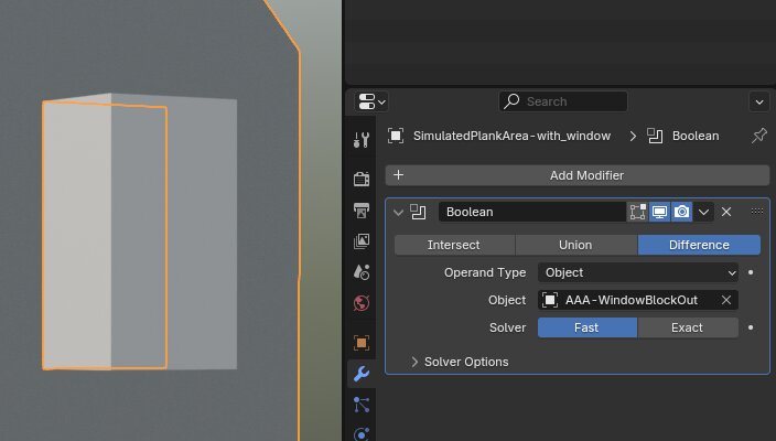
(By the way Blender nerds, I name my Boolean cutting shapes with
AAA- so they show up first in the pull down list in the Boolean
modifier. And after years of doing that, I instantly recognize such
objects for their intended purpose.)
Geometry Node Overview
Now we have defined the face that needs to be covered with regularly arranged geometry. This face can be quite complex — in the case of our house wall, it could have windows and doors and roof angles. Now it's time to put the siding geometry on the wall face using geometry nodes.
To give you a rough idea of what's involved, here's an overview of the node setup.
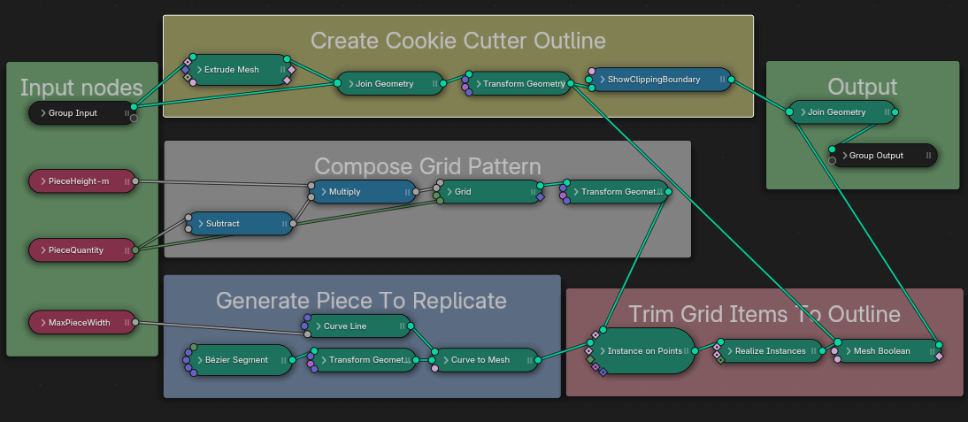
I'll include more details at the end for people who are interested in recreating this kind of setup. For normal people this should convey the main strategic approach to creating a system like this.
Test Result
So what can we do with this? Here is the original mission of getting a sensible system for applying siding to simple house wall definitions.
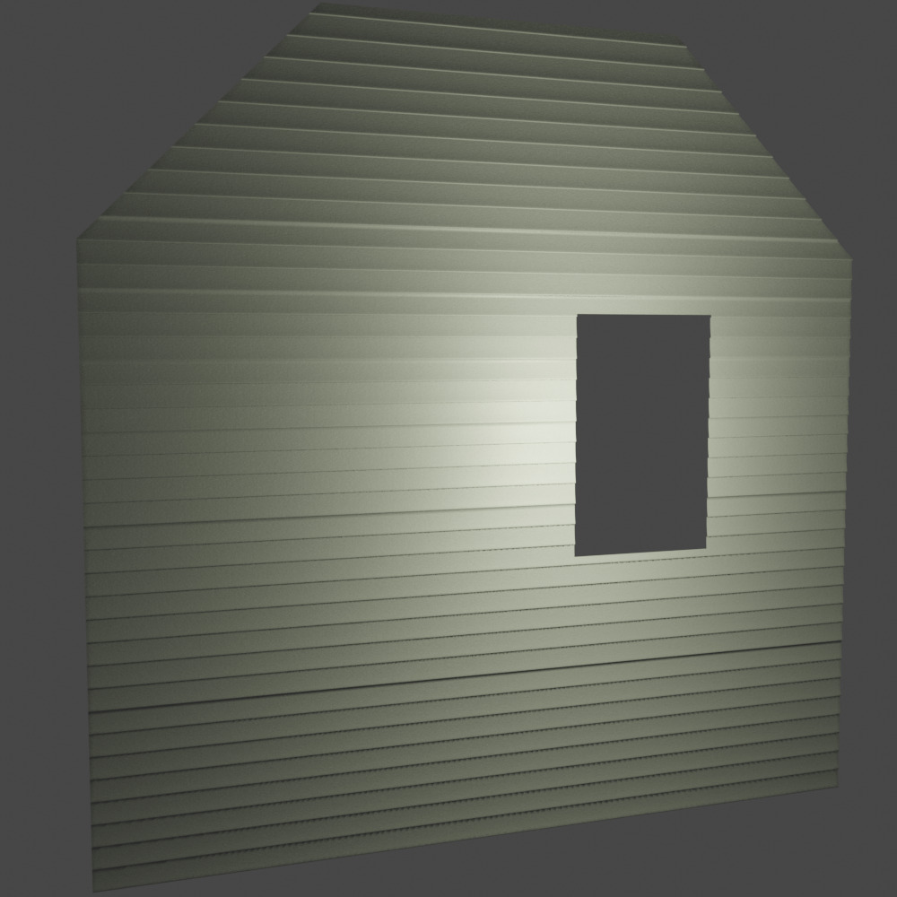
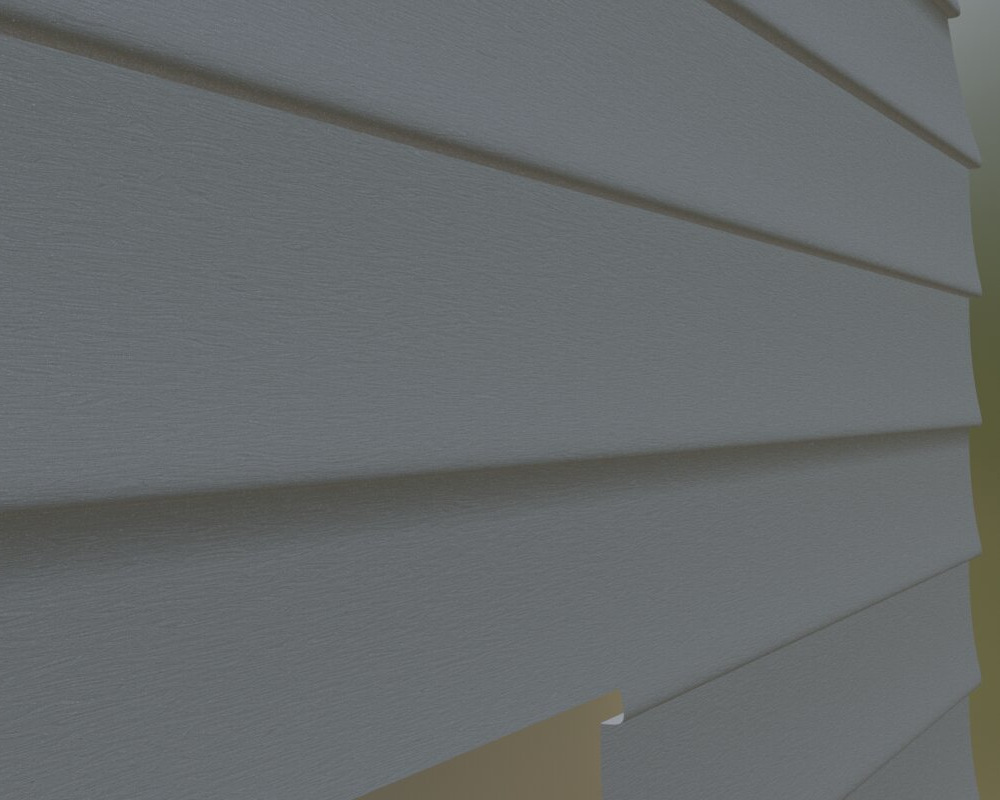
Here's a closer look showing that I actually created a procedural material with the faux wood grain on vinyl. But the important point here is that the siding's complex shape is all synthesized on the fly too. A faux asset for a faux house part!
That seems to work very well. How about the spaced barn boards like I show in the reference photos? Here is a very simple scene of a barn I threw together to show how this kind of system can instantly add a lot of detail to what is really a very simple geometric model.
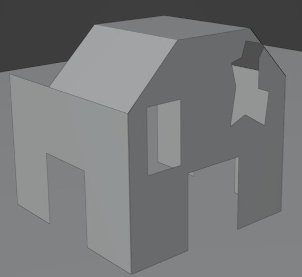
As you can see there is nothing complex about the construction of this barn. All the windows and the broken area were blocked out with quick boolean modifiers making them easily repositioned and modified. Switching from horizontal siding to vertical boards is quite simple. Once I applied the geometry node setup as described, I can get results like this rough animation I threw together .
This shows the results in different lighting and views. Note at the beginning how the boards have a proper thickness. Remember, this barn model is exactly the simple one shown above. All the geometry of the boards is magically generated on the fly. That's the power of geometry nodes!
Other Potential Applications
Hopefully this technique inspires you to consider the possibilities of procedurally generated geometry. This technique is quite powerful and I think it can be applied to even fancier situations. I'll leave you with some other possible applications for techniques like this. Maybe you can think of more.
- Slightly crooked items - My house's real siding is definitely not perfectly horizontal or aligned! By doing some very slight random transforms I think that ostensibly regular objects can be made to look more natural like they were installed by humans and not robots. It can help sell the look of age and wear.
- Randomly selected from objects - Imagine that a fake wood laminate floor comes with a finite number of patterns. Geometry nodes and my technique could randomly pick one of the, say, ten patterns for each board placement. This would help you spot how repetitive the pattern might become and how much care would be needed to avoid bad looking placements. Or randomly go through placement combinations until you find one you like.
- Semi-random placement - Sometimes objects seem kind of scattered around but they are actually installed with some kind of logic. One example would be a procedural way to generate and place cemetery headstones. You could have adjustments for how disordered you want the headstones to be.
- Some randomly missing elements - Sometimes some bricks are missing from decaying buildings or ruins. Geometry nodes could allow you to place the bricks as described but leave them out if a generated random number exceeds a threshold.
- Hand packed tessellating surfaces - I'm undecided about the feasibility of creating surfaces like the cobblestone streets (shown in my texture example). A real cobblestone street or a stone wall is constructed deliberately and with some rules in mind, but there is also a lot of randomness. What makes this hard is making sure everything comes out nicely tessellated. I suspect it's doable and valuable since so many game assets use this kind of look, e.g. castle/dungeon walls, rough paving stones for roads, British style stone walls, etc.
Geometry Node Details
I'll include a complete description of this node setup here so that Blender people can try it themselves. Normal people can skip this part, unless you're especially curious about the details.
Here again is the general overview of the geometry node system organized into tidy groups.

And here are the node groups expanded and explained.
- Input nodes accept the face to cover with the grid object. In our example, the face is a house wall (with windows cut out and doorways and roof lines shaped properly). The other inputs are specifications to synthesize the grid object — in our example, each piece of siding.
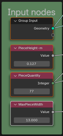
- Create Cookie Cutter Outline will extrude and shift the input face (e.g. the house wall) along the normal a little bit so that its outline becomes kind of like a 3d cookie cutter shape. You can think of it as making a stamp with which to cut out the final shape of the house wall.
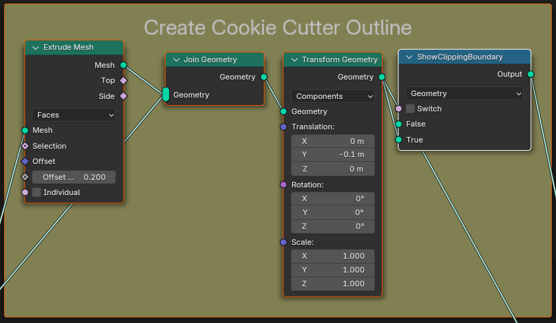
- Compose Grid Pattern takes some of the input values and constructs a grid on which to place the siding.
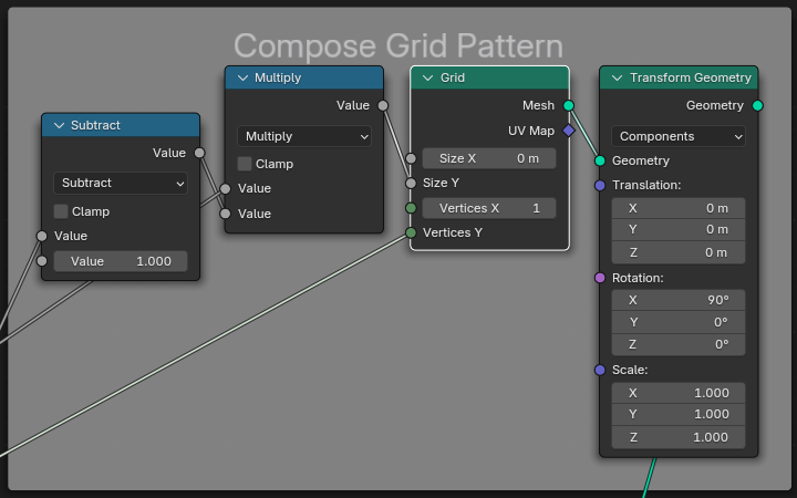
- Trim Grid Items To Outline will first place all the grid items (siding panels) onto the rectangular grid. Then it will take the rectangle of siding and stamp out the house wall's shape, trimming any overhang. This uses a Mesh Boolean node to do the trimming. The result is that none of the siding which was on a rectangular grid will extend past the boundaries of the wall cookie cutter shape.
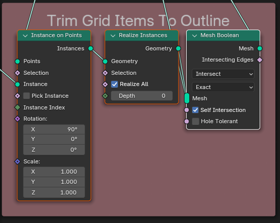
- Generate Piece To Replicate is optional. This node group actually synthesizes the siding profile from a Bezier Segment. It is also possible to just explicitly model your grid item and use it in place of this node group. But this shows that you can not only position items on your surfaces; you can also synthesize those items from nothing. This has the added advantage of being easily modifiable and letting the software do the math so that errors are minimized.
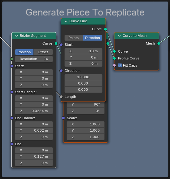
- Output is the resulting wall composed now of properly trimmed siding shapes. There is a join geometry so you can optionally toggle the cookie cutter shape being used for trimming and troubleshoot that.
