(Note that this is a long technical article that engineers and computer science people might find interesting. Everyone else is encouraged to at least scroll down and look at the images which tell the story at a higher level and are pretty cool.)
Whenever I talk to people about machine learning or AI, I can guarantee that the conversation will be well worth their time because of one tiny piece of crucial advice I always give. That advice is:
If you do not see how an AI system fails, you do not properly know how it succeeds.
Seems simple and almost obvious, but the world is full of AI hucksters trying to squeeze money out of credulous VC whales by sweeping the inevitable failures under the rug. That’s all AI systems — they all fail in some way, often spectacularly and comically.
So that’s my AI golden wisdom for you — learn from the mistakes. This is not about AI or machine learning at all. No neural net voodoo is at work in any part of today’s topic which is the magical art of photogrammetry. (Well, as a semantic segmentation specialist, let’s leave that exotic variant for another day.) However, my golden wisdom about evaluating AI applies equally well to photogrammetry. And today I will show you some failures!
First, what is photogrammetry? Since airplanes first started flying over mountains, people got the bright idea to take photos and try to figure out how tall the mountains were from the photos. Extracting 3d data for topographical maps from 2d aerial photography was one of the first main applications of photogrammetry. This discussion is about the more generalized modern automatic technique using computers, an idea I’ve been interested in for a long time.
Way back in the early 1990s, I was working in a machine shop (i.e. 3d printing for steel) and I was making lots of 3d computer models and programming CNC machines. I also had a hobby of photographing classical sculpture. With that background I wondered, is it possible to have a computer automatically convert a photograph into a 3d model? The question for my entire pipeline basically was, can a computer sculpt? I dreamed of showing a computer a model and having it carve that subject out of steel. I decided at that time that, yes, it was plausible. I had no idea how to do it of course! Though far from established mathematically, I reasoned that if some human could look at a subject and proceed to carve it convincingly into a block of marble, it must be possible to take 2d images of a scene and produce 3d models from them.
It turns out I was correct. We know this now because, 30 years later, it is a highly refined process that is mathematically well explored and implemented. Photogrammetry is exactly a technique for creating 3d models out of 2d images. When I pondered the problem long before people had ever seen digital cameras, I got stuck on how concave features could be ascertained. But with full rich photographic bitmaps, there are some clever tricks that solve this problem.
Here’s a rough basic rundown of how the clever modern process works.
Step One - Collect a lot of photographs of your subject from all angles. Consistent camera optics are helpful. Redundant coverage of the same part of the subject in multiple shots is important. Anywhere from a handful to a couple hundred images are needed depending on the goals for the final outcome.
Step Two - Feature detection is a process where an algorithm looks for distinctive patterns and notes a summary of that pattern along with its location. One common one is known as SIFT, the Scale Invariant Feature Transformation — sounds arcane, but the scale invariant part just means that it can still spot a feature even if you change camera angles (the scale). It transforms the "features" into something usable and comparable. These features tend to be something like a histogram of gradients, i.e. the distribution of a certain profile of intensity changes.
Step Three - Feature matching looks at all the feature summaries found in all the photos and tries to figure out if any are showing the same thing but from different angles. These features will never be identical so there’s some adjustment for how sensitive a match needs to be.
Step Four - Figuring out where these matched features are in space is called Structure From Motion. Imagine someone takes a bunch of photos of a football goal from different positions (the "motion" part) in the stands. The feature detection of step two notes where the corners of the lines and goal posts are. Step three figures out which are which. This step now triangulates what the geometry must be for this previously calculated information to be rational. What I find impressive is that this step computes where in the stands the photographer was when each photo was taken!
Step Five - With the camera positions figured out, the process can now scan across all of the pixels of two (or more) images and mathematically compute where two cameras shooting rays (think of snipers looking through scopes) to that part of the image would intersect. Small corrections to best match what is actually found at those pixels help refine the depth. Doing this with thousands of data points, a very accurate model can be constructed, even with concavity (though not complete occlusions, like deep inside of a shoe).
Step Six - With a lot of data points known about the surface of the reconstructed geometry, typically a usable mesh model is automatically generated. It turns out that’s an entire science and art itself.
Step Seven - Since we have access to dozens of photos of the subject it’s a reasonable time to lift texture information. By pulling color swatches out of the photos, and wrapping them just right, we can have an automatically colored model as well as just the mesh geometry.
That’s the process and I’ve been very keen to try it since I first heard about it! At first I struggled with the software that people were using. I’ve tried several approaches and had a lot of problems with dependencies and crashes and compatibility issues. Finally recently I had a need/desire to have a model of my new ice skates. I wondered if I could give photogrammetry another try.
The first thing I did was load up a set of test images from the British Museum. It turns out that photogrammetry is used extensively to accurately document and study archaeological artifacts. In this case, a skull. I ran the skull image set through the software package Meshroom and was delighted that it finally works now! Here was the result I got.
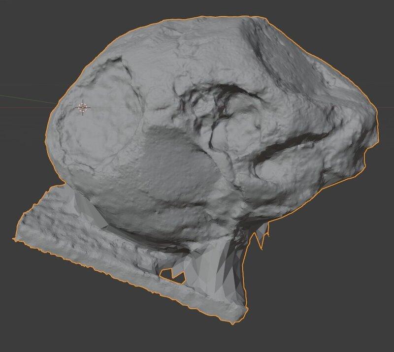
The geometric detail, shown here in Blender, was amazing and the textured result was even more astonishing!
Excellent! Buoyed by such a great success I was ready to dive in! What I didn’t realize is that I now suspect that this skull data set is one of the ones carefully used in the testing of Meshroom’s default settings. My dreams of an easy win were quickly shattered.
I knew my subject was going to be a challenge. Photogrammetry really likes things with some good obvious texture features. Archaeological relics are usually perfect since they’re not usually completely smooth and new. Being scratched and dirty is a plus! Also photogrammetry becomes seriously confused by reflective or transparent materials. My subject had a lot of carbon fiber at the heel which on the one hand has a lot of texture, but it is also shiny and reflective. The reflections, which appear to move around the object’s surface, cause quite a bit of trouble. Also the top (fake) leather is polished to a high even gloss. I discovered that Velcro may actually be the worst material possible. To help facilitate the process I applied a bunch of little masking tape markers all over the skate. I also used 3m 658 Labeling & Cover-up Tape which is great stuff — like a whole roll of the sticky part of PostIt notes. If you can’t add markers or clean it up with post processing edits, that’s a challenge. You can actually buy spray cans of stuff that apply an opaque powder on objects to achieve better results with photogrammetry; it then disappears in a few minutes! Yes, that’s a real thing! These markers didn’t adversely affect my goals and clearly helped a lot with the process.
A few months back, I had purchased a new camera for projects just like this. This photo shows my new camera (a mirrorless Canon EOS M50m2, very nice) and the abysmal photo quality of my stupid telephone.

Thinking that just feeding the software some high quality images would solve all the problems, I shot 100 or so crystal clear 6000x4000 images of my subject. And…. Complete fail!
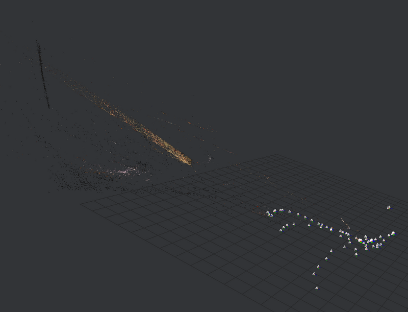
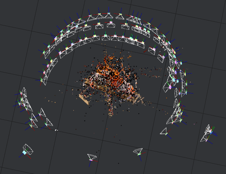
Since it took about 10 hours to run that, I decided to back off and downsample my images to 800x533. Amazingly this produced some kind of rough model in about 10 minutes.
Once I cleaned up some images with questionable views, I was able to get it to this.
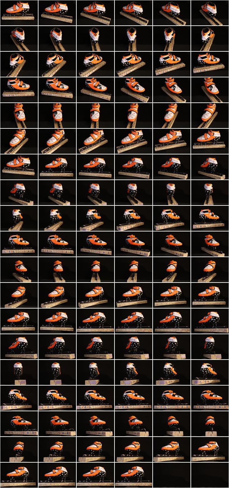
Great! Ok, that is on the right path! I refined my setup and re-shot my images to make sure my set was very clean and my camera settings were perfect. To give you an idea of what these images are like here are thumbnails of my complete input set.
Unfortunately, I was still getting results like this with full resolution images.
Realizing that the problem seemed to be that the software was detecting features of my background I wondered if I could somehow magically remove the background. I shot some images of the setup without the subject and did exhaustive testing of ImageMagick’s compositing tricks. This is a summary of the subject as Src and the clean plate image as Dst.
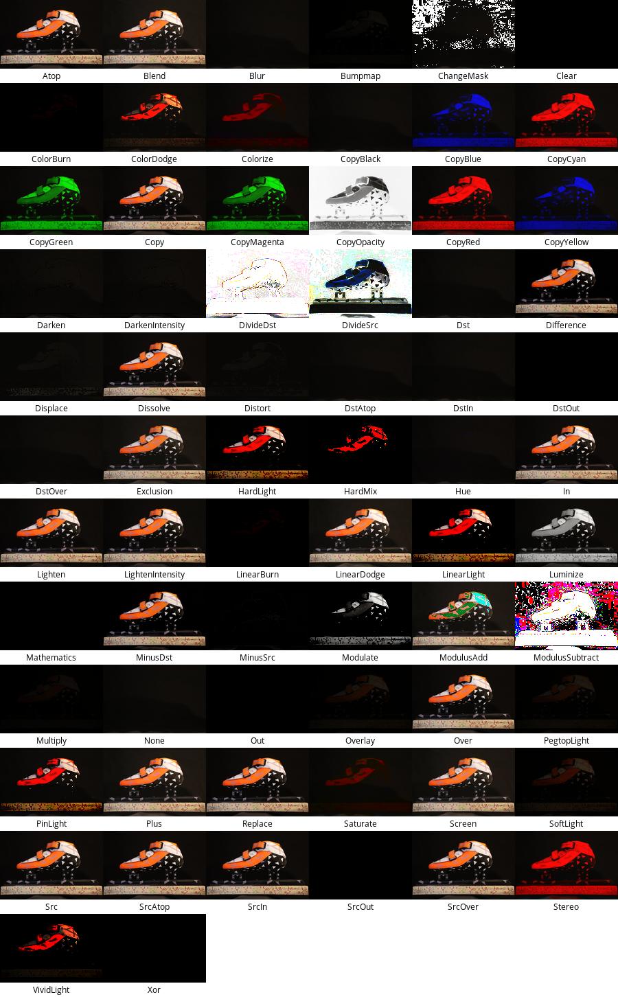
Ultimately I never found a magic bullet for completely cleaning up the background automatically but this image is so useful for ImageMagick projects, it’s good to leave here for reference. I did come up with some helpful ImageMagick compositing tricks that I recorded on my photogrammetry notes.
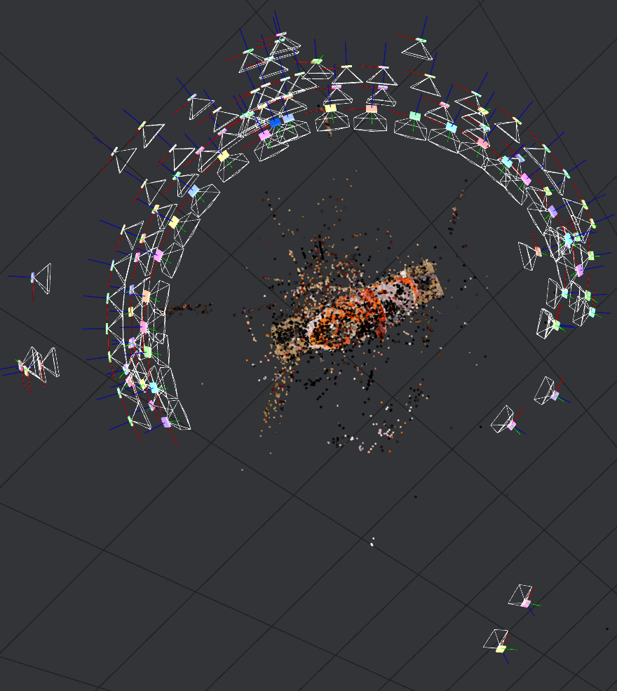
As you can see with the ImageMagick efforts, I was in full berserker mode not really ready to take no for an answer - I was going to make this work! So I hand edited half of the 112 images. Yup. At least I got very quick at doing it. And here’s what I got.
Since that was decent and an improvement, I hand edited the rest of the 112. And here is the result of that.
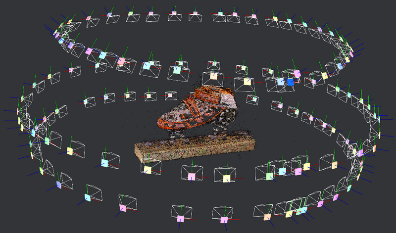
Better. But still very frustrating since I have made my input as perfect as I think it is possible to make. That left only settings. Even though all sources strongly recommend using the highest resolution possible, I started to get the feeling that my input was just overpowering the process. Where a normal data set could be sure of a match if 200 features were identified, my high resolution set could come up with 200 spurious matched features in any random square centimeter of the background. By turning up the required feature matches to 750, I finally started to get results. Of course this sounds easy enough, but remember that each run of this high density data took 10 hours! Finally with the new setting I started to get some acceptable results.
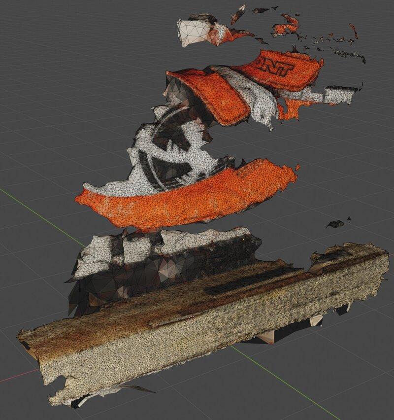
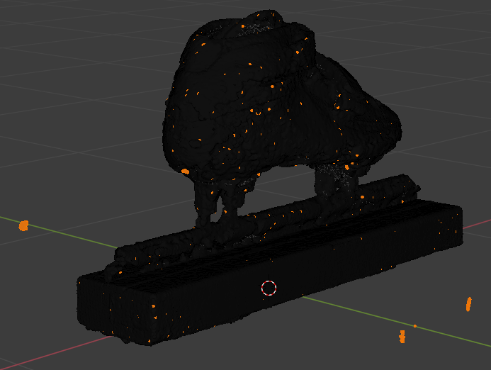
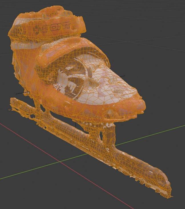
It wasn’t perfect. Here is the resulting mesh in Blender highlighting all the unconnected geometry (which obviously can’t be right).
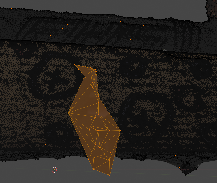
To give you an idea of how fine of a mesh we’re talking about, here’s a close up of one of the worst of these regions. The circles are Sharpie marks I put on the board to help with feature detection.
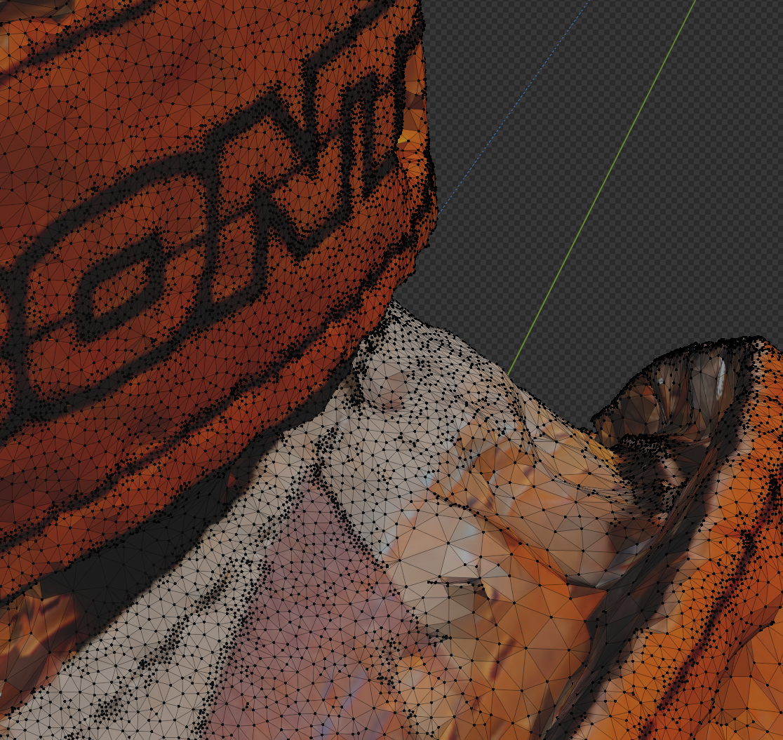
Here’s another look at the level of detail, this one showing the texture information applied.
Finally, here is the model created from 112 high resolution photos.
Yay! That is an amazing model, but actually not terribly useful. After picking up so much detail, I now needed to thin down the mesh to something hopefully still highly accurate, but less unwieldy to work with. Finally, using Blender modeling magic I was able to produce this usable model with a very modest polygon count (from 941k vertices and 1882k faces down to only 14k vertices and 16k faces).
It still looks great!
You can see that it looks like there are chunks missing from the model. Because there are. But I could actually clean that up by hand if I wanted to. But obviously you can see that I’ve sunk way, way, way more effort into this model than was strictly necessary for practical use. This was really a learning exercise and there was no point to me re-sculpting the mesh to clean up defects that reflect the limitations of the photogrammetry process. I have a perfectly usable mesh for my original purpose. I’ve learned a lot. And the process and results are incredibly cool!