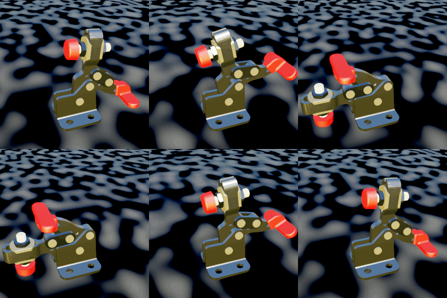
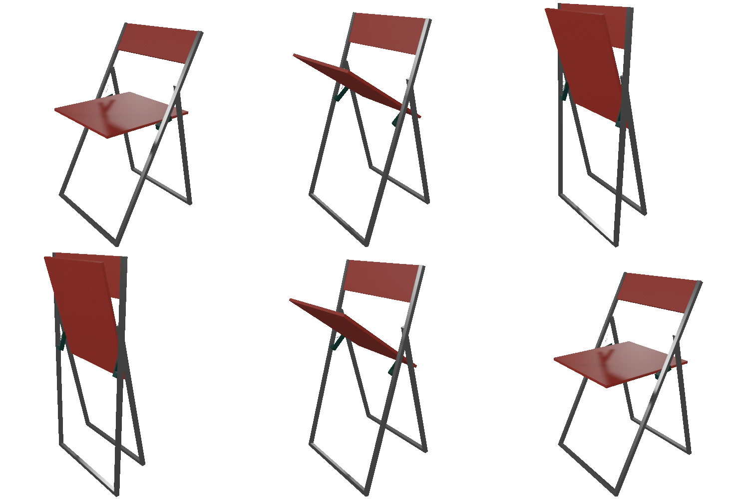
I’ve been doing a lot of Blender stuff recently. I feel like I’m on the threshold of being actually somewhat competent with it. I’m not as fast as I was with AutoCAD in the early 1990s, but — wow! — it is so much more powerful! The things you can do are truly amazing and just the kind of things I’ve spent much of my life dreaming about.
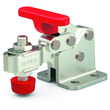
A couple of weeks ago I had the thought to make a holding fixture that could use some holding clamps. One thing I learned as an intern back before the early 1990s was that the best clamps for custom fixtures was the De-Sta-Co brand. I specifically took an interest in the 307-U model. Here’s their catalog image.

Checking out their catalog, I noticed that, like any non-terrible
component manufacturer, they offered CAD files of their products.
Annoyingly, although they offer many CAD formats, most of them are
proprietary and can be assumed obsolete all too soon. None of them
(that I could figure out) were compatible with Blender. I was however
able to import a STEP
(.stp) file which I think is an ISO standard, into FreeCAD and then
export that out as just triangle geometry in an
.stl file that
Blender was happy to read.
The model was all one big blob, but I found that using l to select
"linked" items did actually allow me to select only each part of the
assembly and separate the geometry into each of its subcomponent
parts. I was slightly pleased with myself once I’d done that and
rendered it a bit. However….
Wouldn’t it be super cool to animate this properly? After all, if I’m going to design with it, I do want to know where the open and closed positions are. And probably all the positions in between. The problem is that this clamp is what is known in engineering as a four bar linkage.
If you connect the ends of three drinking straws with safety pins, you’ll have a triangle that is as rigid as such a system can be. But if you add a fourth straw, it all suddenly becomes floppy. If you have four straws and they are all different lengths, it can become tricky to figure out exactly how moving a straw with respect to another will affect the other two. It turns out that Blender can solve this problem using its inverse kinematic solver. This heavy duty feature is mostly used to pose body parts while animating characters. Instead of using "forward kinematics" to directly specify thigh angle, then knee angle, then foot angle to take a step, inverse kinematics allows you to specify that the foot goes here and the leg’s joints need to be sensibly calculated to fit. If you’ve ever experienced dance instruction or sports coaching, you know this kind of thing can involve a lot of ambiguity and Blender has a lot of fancy tools to resolve it.
Fortunately, this case is much simpler than typical physiology based animations. Normal people can admire the final product and you’re done. Thanks for reading and have a nice day!

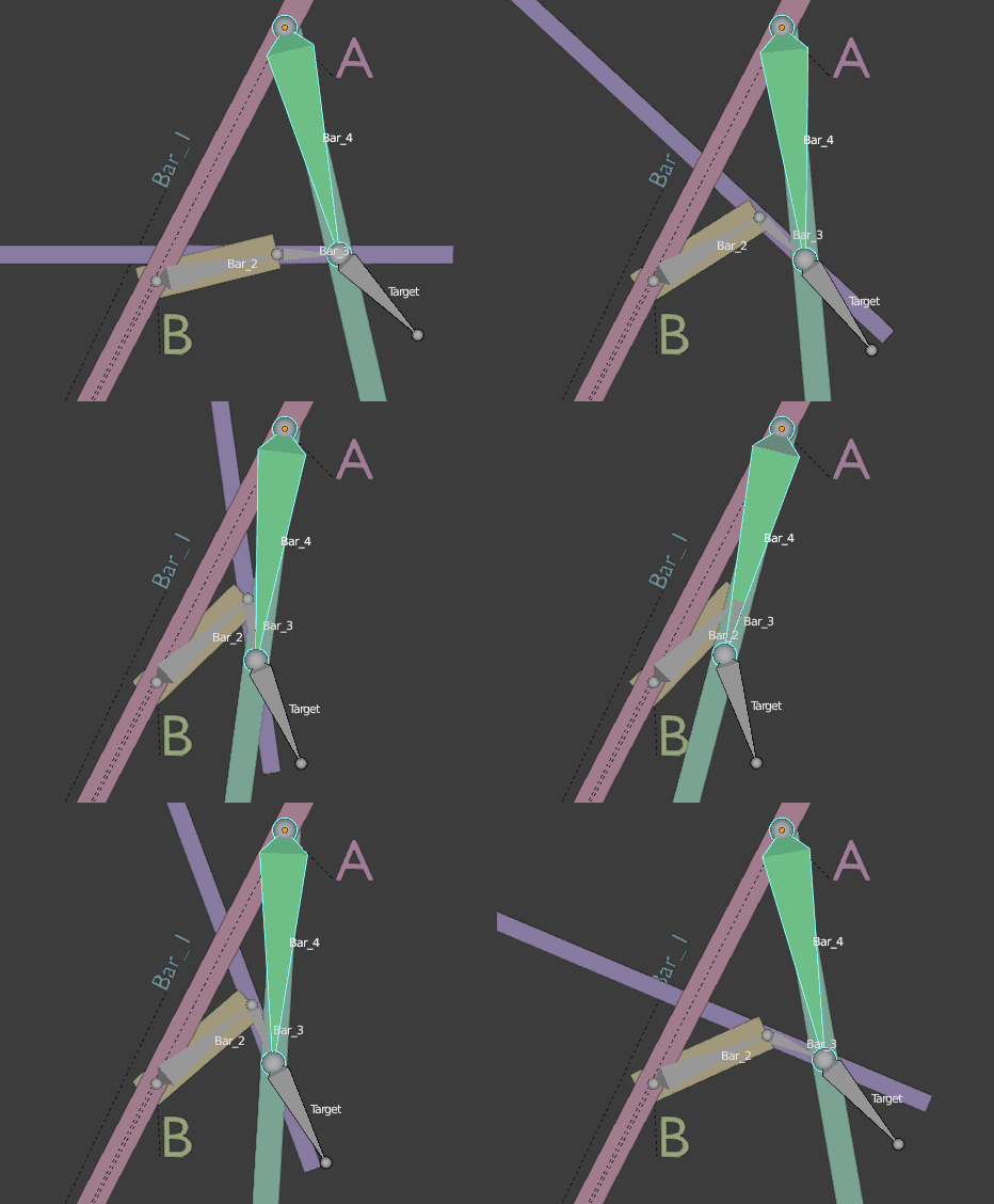
Blender users looking for a detailed guide on How To Rig A Four Bar Linkage, can use the following procedure (also found in my Blender notes).

-
Create an armature object with two connected bones (generally extrude the second bone in edit mode). Call this armature A. Call the head (fat) end bone "Bar_4" and the tail end bone "Target". Bar_4 will be the handle that you position.
-
Create a second armature like the first ([S]-d duplication works). Call this armature B. Call its head end "Bar_2" and it’s tail end "Bar_3". These are the bars that will be calculated and not explicitly set.
-
Mentally note that "Bar 1" is simply the span between the head of Bar_4 and the head of Bar_2 since those heads do not ever move. To visualize a practical example, imagine that Bar_4 is the door which you want to control in your scene; Bar_2 and Bar_3 are the moving parts of the door closing mechanism; Bar_1 is simply the door frame between the wall mount for the closer rods and the door hinge.
-
Move the tail of Bar_3 so that it is in the same location as the tail of Bar_4 (which is also the head of Target).
-
Select armature B and go to Pose Mode.
-
Select Bar_3 and look for the "Bone Constraint Properties" tab. Click "Add Bone Constraint" and choose "Inverse Kinematics". Choose armature "A" for the Target. Choose A’s bone called "Target" for the "Bone".
-
It might be smart to add a chain length of 2 since that seems to be correct. However, I noticed that leaving it at zero also did actually work anyway for some reason.
-
You should now be able to rotate armature A’s Bar_4 bone and have Bar_2 and Bar_3 do the right thing ("bar 1" is implied as part of the stationary part of the model).
-
Since you’re not trying to animate bones as the final goal, you’ll want to hook the rig up to your actual model. Select the real/rendered object that represents one of the moving parts, one of your part’s bars in the linkage.
-
Shift select the armature. That will allow you to change to Pose Mode with some armature object also selected as the non-active selection.
-
Now that you’re in pose mode you can and must select the specific bone with a shift click. Once you have the specific bone as the active selection and its real world object also in the selection, parent with [C]-p. Choose "Bone" as the parenting style (Not "Bone Relative"). Repeat this step for any other bar geometry you have.
-
Pose Bar_4 and sit down and relax!
