Emphatic Camera Calibration With OpenCV
:date: 2017-04-02 11:24
The Problem
I walked up to the cashier at the dollar store and asked, "Hi, would you mind if I took some pictures of your floor?" Fortunately, I have a lot of practice being treated like a weirdo. But let's start at the beginning.
In my recent educational project I've been studying camera calibration. This is pretty neat but for technical applications, it can be mathematically essential. Consider this image which I took today with my dashcam.
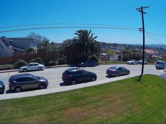
It has an admirable field of view, but that comes at a cost, a medium fish eye (technically barrel) distortion. Note how the wires seem to float weirdly. The sidewalk and grass cut lines seem very curved although they are really straight. To explain what the point of all this is, imagine we were very concerned to know if this photo is at the top of a hill. It would be hard to determine the slope of the road with all the crazy curves going on.
The trick for fixing this is to use the same camera with the same settings that took this photo to take some photos of reference scenes where we do know the geometry. Then by matching up the real geometry we know with the geometry we encounter in photos produced with this camera, we can start to map a mathematical relationship between reality and what winds up in our photos. Once we know how this transformation works, we can transform a distorted image into something with more accurate geometry.
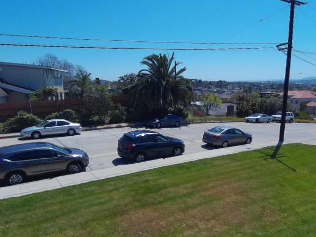
Notice how the horizontal wires now seem to hang in a proper catenary curve. The utility pole and the near sidewalk are now straight. However, if you take a straight edge to the far side of the road, you'll notice there is still a curve there. The reason for that is exactly what we're looking for — this is just at the top of a steep hill and there really is a downward curve to the road here! By eliminating the lens distortion we can now see real curves accurately.
The Solution
The impressive OpenCV library (CV stands for
Computer Vision) has several features to facilitate this kind of
camera calibration. These functions require images of a well
understood reference scene. Although this can take the form of small
circles
in specific layouts, the most common target is a grid of alternating
black and white squares resembling a chessboard. The idea is that it
is relatively easy to identify the intersection of a black and white
square over a white and black square. Once these points are found they
can be mapped to the regular grid which we know the chessboard is
defined to have. Scale is not too important so the coordinates of the
theoretical grid can just be (0,0), (1,0), (1,2), etc.
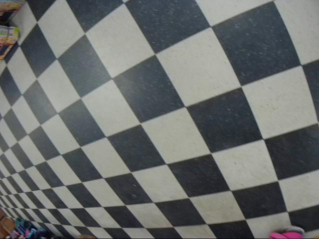
The first problem I faced was obtaining a large very flat chessboard. I had walked over to the dollar store looking for something to make one with. I was looking at a wide roll of black duct tape and wondering if I could use that when I noticed I was standing on a perfect black and white grid of 12 inch tiles. I definitely did look odd walking around the store with my laptop and my dashcam taking photos of the floor. But as I said, I'm used to that.
I collected 38 images of the floor. Here are most of them to give you an idea.

This whole plan rested upon an assumption I had made based on what is theoretically possible. In practice, when people do this, they tend to print out a grid and photograph it in various orientations. Here is an admirable example of this technique. But check out this particular calibration shot.
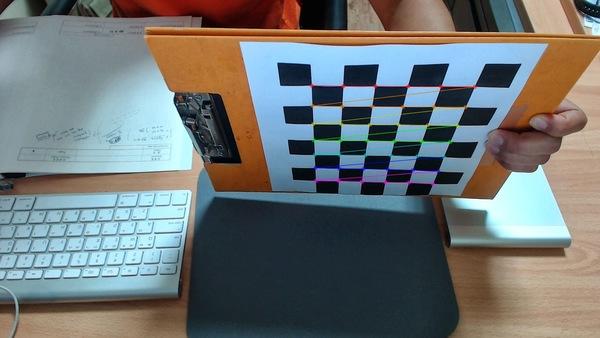
What bothered me about this normal approach is that it's not completely easy to manufacture a perfect reference specimen. Sure, your laser printer is extremely accurate but 8.5x11 inches is pretty small when the intended use of my camera will be to capture images on the road. And there is more to it than just getting your squares lined up — they must be flat! Notice how in the previous image, the guy mounted it such that we can clearly tell that it's not flat (e.g. along the top edge). Flat is one of the assumptions necessary for doing this properly.
This is why I thought using a floor would be convenient and potentially superior. The big question was would it work? The answer is yes it does! And they all lived happily ever after. This is a good time for normal people to pat themselves on the back for making it this far and stop reading. Have a nice day.
Technical Details
I did end up discovering a lot of things about this process which, if you're still reading, should be fairly interesting. I started out having OpenCV look for a grid with findChessboardCorners and the main problem was immediately apparent. I did not find any chessboard corners! None. I checked several images. Nothing.
In the official documentation for findChessboardCorners it says this ominous thing.
The function requires white space (like a square-thick border, the wider the better) around the board to make the detection more robust in various environments.
Is this true? Dang. This was the fine print I had read only after collecting my images and discovering they didn't work. How disappointing! I had a hard time believing this because, well, because it turns out that it is wrong. If reading the manual was the correct thing to do, then there was still a possibility to make my images work. I could hand edit them so that they had this required white border. After asking about this on a forum and others independently had that idea, I figured it was worth trying. So I laboriously used Gimp to remove all pixels around the core group of intact squares for all 38 images. Here are some examples of what that transformation looks like.
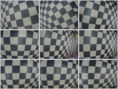
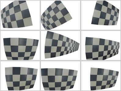
Full of curiosity, I ran findChessboardCorners on some of the newly
edited images. Nothing! No grids found. This was getting very
discouraging. I had hand edited these things, I might as well check
all of them. And that's when I discovered some very interesting
things.
Finally, while checking my entire set of 38, I found a grid. Whew! Comparing it with the unedited image, I also found a grid. What? This was making no sense. One of the complications for me was that you must specify the grid size you are looking for. This means that if you think there should be a 3x4 grid in your image, you need to say that up front. Trying different sizes was becoming so tedious I realized, this is the kind of job for a computer!
I wrote a program that iterated through all possible grid sizes and
looked at all images. Now I was finding grids. Ah ha! Turning to the
documentation to figure out what exactly was going on, I noticed the
function had a parameter, flags, which could be set to enable certain
grid finding techniques. I set one of the flags and the grids I
could detect changed quite a bit. Now I added to my program another
inner loop to iterate through all the detection modes.
Running this exhaustive test of the possibilities revealed many interesting things.
Limited Success Editing
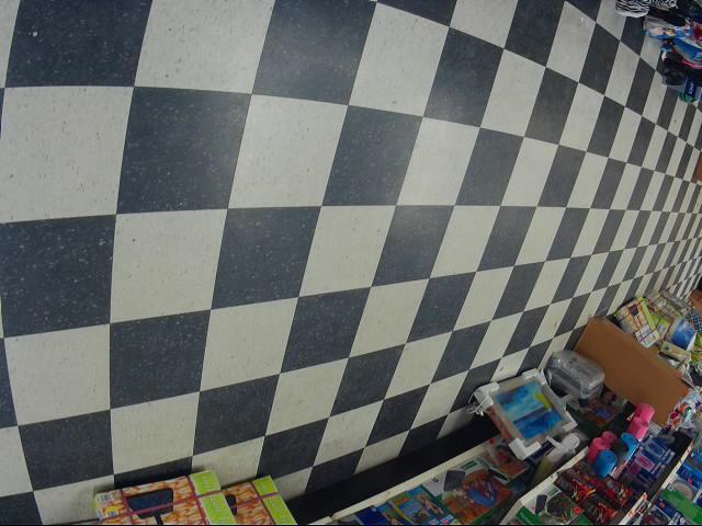
Although I struggled to detect grids at first, it turned out that this was merely bad luck. Only one of my original unedited images failed to find a grid at all. Interestingly, after editing, this one did successfully find a 3x3 even though there is not a 3x3 clear grid in the scene! Here is the original photo from which OpenCV could not find any grid.
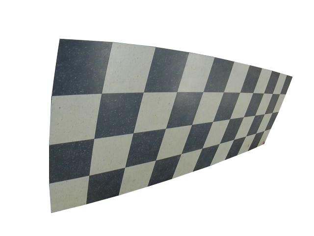
Here is the edited photo in which OpenCV did strangely find a 3x3 grid. I left these images at full size just like I experimented with them if you'd like to have a go yourself.
Editing Actually A Waste Of Time
Although editing out a white space around one image had helpful effects, it was clear that overall, this strategy was a complete waste of time. After editing, 13 failed which had originals that did not fail. Editing basically ruined 34% of my images and improved less than 3% of them.
This image was able to produce a single 3x6 grid after editing.
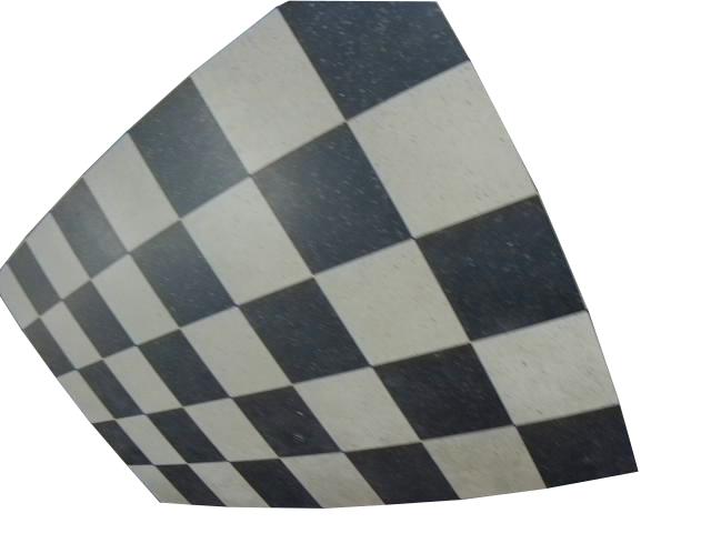
But the original image was able to produce 16 different grids!
Editing to isolate a section of a continuous tiled pattern clearly was a bad idea. Grids were found 604 times on original unfixed images and only 194 times on the same images with a hand edited border.
Minimum Grid
In the set of nine original and edited images I show above, the edits were doomed to fail. The reason is that, according to the documentation, a grid must have at least 3 values in each dimension. I did test this and found it to be conclusively true. No 2xN grid was ever found. I did try finding grids with edited images with plenty of squares and even with a full white border but it was simply much less effective than leaving the original images alone.
Transposition
Since I was doing a time-consuming exhaustive survey of this function, the next question I had was about the significance of the order of dimensions. In other words, if I found a grid with 3x6 would I always reliably find one when searching for a 6x3 grid?
I believe the answer is yes. Every image I found which could produce a grid could produce one with the dimensions switched. This should allow users to not worry about covering both orientations since they appear to produce the same results.
Flags
Although there were many surprises when researching this, the biggest one for me was how much flag settings affected detection success.
The flags work like Unix permissions bits where 0 is no flags set and a 7 is all three of them are set.
- 0 - No flags set
- 1 - Adaptive thresholding
- 2 - Normalize gamma with equalizeHist()
- 3 - 1 and 2
- 4 - Filter out false quads
- 5 - 4 and 1
- 6 - 4 and 2
- 7 - 4 and 2 and 1
There is actually another bit for "fast check" which apparently is an optimizing trick for speeding things up. Since I was just interested in the best results possible without worrying about time pressures, I ignored this.
Here is a summary of how many successful grids I was able to detect when various modes were in effect. Remember, I tried all combinations with all possible (and impossible) grid dimensions.
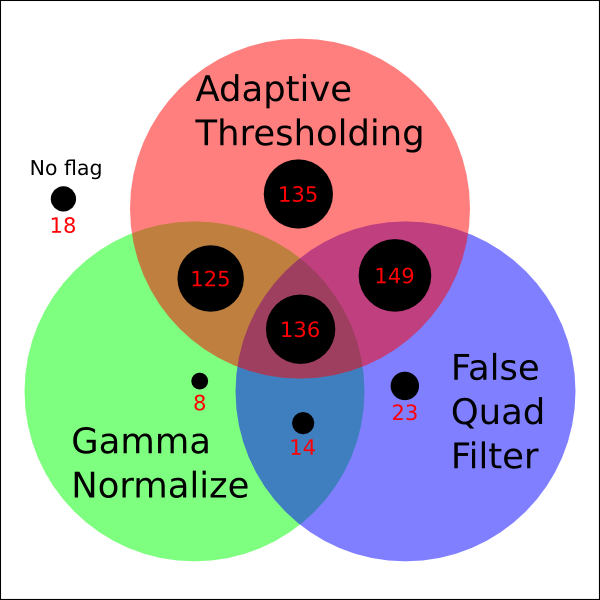
Clearly adaptive thresholding should be considered. Gamma normalizing seemed to snatch defeat out of the jaws of victory whenever it was used. The false quad filter seemed harmless enough and although its improvements were modest, they were improvements. Note that I did not consider the computation time necessary for these modes. Perhaps in a real time situation (localizing a quadcopter with a tile floor, for example) it would be a problem.
Sample Size
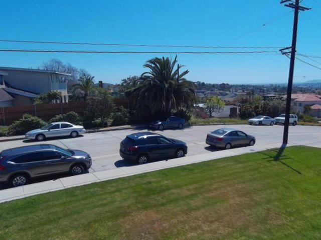
When I was testing, running through all those settings was time consuming. I did many tests where I just looked at a small subset of my calibration images. How necessary is a large set of images? I don't have anything quantified but here is an interesting look at the difference between using 5 calibration images and 38.
My Calibration Program
My final recommendation is to not give up! If you are not detecting grids, it may just be a question of settings. I recommend, especially if you're having trouble or exploring a new kind of target, that you check every possibility for detecting grids.
Here is the program I used to go through multiple images and create the camera correction matrices. It shows how to do the experiments I discuss and should allow you to produce very high quality calibration settings. While most people keep a consistent set of grid dimensions for simplicity, this is not optimal, nor is it the most simple when acquiring images. My program has no trouble using grids of different dimensions as they are found. Note that it may take hours to run this, but since calibrating a camera should only need to be done once it can be worthwhile. Good luck!
thorough_calibrate.py
[source,python]
#!python3 -u
'''thorough_calibrate.py - Chris X Edwards - 2017-04-01

A program to generate camera calibration matrices from multiple source images
using an exhaustive search of every grid shape and scanning mode possible. All
found grids are used to calculate the correction coefficients.

Usage: thorough_calibrate.py i1.jpg [i2.jpg ... iN.jpg]

See OpenCV reference:
http://docs.opencv.org/3.0-beta/modules/calib3d/doc/camera_calibration_and_3d_reconstruction.html
'''
import sys
import cv2
import numpy as np
import pickle

MINDIM,MAXDIM= 3,10 # Checks mxm to MxM inclusive. Less than 3 is invalid.
ofn= 'camera_distortion.p' # Output pickle file name for parameter save.

objpoints= list() # Points of grid in some real world space, z implied at 0.
imgpoints= list() # Points as found in image plane.
for imf in sys.argv[1:]:
    print("== "+imf)
    i= cv2.imread(imf)
    gray= cv2.cvtColor(i,cv2.COLOR_BGR2GRAY)
    for row in range(MINDIM,MAXDIM+1):
        for col in range(row,MAXDIM+1): # s/row/MINDIM/ for MxN & NxM. Shouldn't be needed.
            for mode in range(8):
                found,corners= cv2.findChessboardCorners(gray,(col,row),None,flags=mode)
                if found:
                    print("%d,%d - (%d) - %s "%(col,row,mode,imf))
                    objp= np.zeros((row*col,3), np.float32)
                    objp[:,:2]= np.mgrid[0:col, 0:row].T.reshape(-1,2)
                    objpoints.append(objp)
                    imgpoints.append(corners)
img_size= (i.shape[1],i.shape[0])
# The `calibrateCamera()` function produces:
# dist= Distortion coefficients. (k1,k2,p1,p2 [,k3 [,k4,k5,k6], [s1,s2,s3,s4]])
# mtx= Camera matrix. [ [fx 0 cx] [0 fy cy] [0 0 1] ]
ret,mtx,dist,rvecs,tvecs= cv2.calibrateCamera(objpoints,imgpoints,img_size,None,None)
# Something like this in the pickle object.
# camdist_p= {'dist': array([[-.233,.0617,-.0000180,.0000340,-.00755]]),
#             'mtx': array([[560.33,0,651.26],[0,561.38,499.07],[0,0,1]])}
pickle.dump({'mtx':mtx,'dist':dist},open(ofn,"wb")) # Save these parameters.
UPDATE 2022-05-09
Here are some excellent resources related to this topic!
- libdetect - Another approach to finding calibration patterns.
- Professional calibration specimens.