This is the project page for my C.A.R. project. C.A.R. stands for Cars Autonomously Racing. The central idea here is to create a platform on which to explore various techniques for controlling autonomous vehicles in a racing environment. Since I can not afford an F1 car or even an ordinary one to experiment on, my goal is to create a system using inexpensive remote control toy cars. The entire racing infrastructure should cost less than $30.
There are many goals of this project.
-
To create a real world platform for race car AI development very similar to the simulated environment provided by TORCS in the Simulated Car Racing Competition. See my TORCS notes for more info on how that is used in the SCR.
-
To create compelling AI drivers that can beat humans in a real car racing task. Even at this scale, it would not be a trivial accomplishment.
-
To create a real world testing ground that can then be simulated. The purpose of this would be to compare whether simulated versions of the environment behave similarly to real ones. The point is that if you have an AI driver and it performs well in computer simulations, is there a context where that can be proven to translate correctly to a real world setting. This has big implications for autonomous car development.
-
Fun!
The Car

Input
Instead of the normal sensor package found on most autonomous cars, for this project it is practical to simply have a video feed of the entire track from a top down perspective. The camera to use is a PlayStaion Eye camera. These are basically USB web cams but with very high frame rates.
Cost: $9
Tracking With OpenCV
See my notes on OpenCV.
Output
Parallel Port Interface - IS DEAD
In theory, there are several ways this could be done, but the parallel port is known to be a classic for easy use with simple projects. Since the computer only needs to control 4 TTL circuits I started with a USB to parallel IEEE-1284.
Cost: $5
GPIO
A more modern approach would be a device using the FT245RL chip (pdf datasheet). This chip converts USB data into TTL signals. Here is a complete breakout board featuring the FT245RL with USB connector.
This implementation from DLP Design looks pretty good too especially the schematic on page 13 of this PDF.
Unfortunately, it’s very hard to get any information about how to use such a thing. Here is a Lithuanian post which shows a sample circuit. It is also notable for expressing the exact same frustration with the parallel port that I’m seeing now. Here is a similar project in Polish driving relays.
Driving this thing from Linux could be a trick too. Check out libftdi for a possible solution. This is a good article on bit banging which discusses the strategy for getting around the dearth of parallel ports.
Here is a project to control USB with Python.
My LED notes may come in handy.
Numato 8 Channel USB GPIO Module
This is the way to go! Although it may be more popular to use an Arduino or Raspberry Pi, this task simply does not need another CPU to process anything. All of the logic should be handled immediately and directly by the host computer. I’m sure using a small board with its own microprocessor would be fine, but this GPIO board’s processor is specialized to do only the task at hand.
There are 8 connectors on the module labeled 100-107 and one (farthest away from the USB conneciton) labeled GND.
The driver for Linux seems to already be present and it is called "cdc_acm". Plugging it in can be sufficient to load the module.
[21012.689869] usb 1-1.3: Product: Numato Lab 8 Channel USB GPIO Module
[21012.689877] usb 1-1.3: Manufacturer: Numato Systems Pvt. Ltd.
[21012.691950] cdc_acm 1-1.3:1.0: This device cannot do calls on its own. It is not a modem.
[21012.692011] cdc_acm 1-1.3:1.0: ttyACM0: USB ACM device
The device can be accessed at /dev/ttyACM0.
Though the kernel tells us that this "is not a modem" it can be interfaced in a similar way to modems. This means that it can be communicated with like any serial device/modem using something like minicom. Because it is really USB and not proper serial, you don’t have to do too much configuration.
Configure minicom by
-
ctrl-a -
z -
ofor "cOnfigure Minicom" -
"Serial port setup"
-
aSerial Device set to/dev/ttyACM0 -
eBaud -
candEnterfor 9600 (just noitced 19200 is default in sample code) -
ffor Hardware Flow Control to be "No" -
"configuration" menu do "Save setup as dfl"
Apparently it is essential that hardware flow control be set to "off"
(which was not the default). Once you change the settings and save
them as default, it is helpful to quit (ctrl-a, z, q) Minicom
and restart it. After that, you should see a > prompt. Then you can
start trying commands. The first ones to try is the version and id. Be
careful when you type since backspaces confuse the chip you’re
communicating with.
>ver
00000007
>id get
00000000
Once that is going well, put a resistor and an LED between pin 100 and pin GND and send these commands.
>gpio set 0
>gpio clear 0
The 0 is the channel number. These commands should turn on the LED and then turn it off. Yea!
You can write to all the pins in one go with something like this.
>gpio iomask ff
>gpio writeall ff
>gpio writeall 00
>gpio readall
01
The iomask command can protect pins from being changed. Here with
ff all pins are being unmasked so they can be written to. The
writeall command writes the byte specified so that the 8 bits are
high or low as indicated. The readall command shows what lights are
actually active.
How about Python control. Of course. Easy. This program turns the
channel on. Change set to clear to turn it off.
#!/usr/bin/python
import serial
s= serial.Serial('/dev/ttyACM0', 19200, timeout=1)
s.write("gpio set 0\n\r")
s.close()
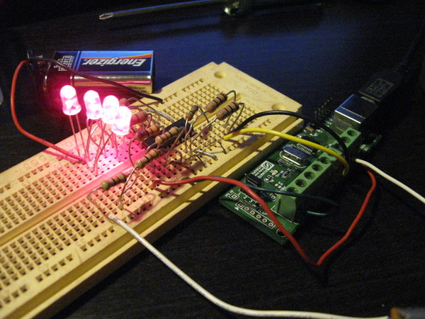
Optoisolation
To have a GPIO control switches of a miscellaneous and uncharacterized circuit requires some kind of interface. Since the current of the remote control circuit is unknown (though most likely extremely small) it is good to electrically isolate it. It looks like optoisolators can do just what is needed. Essentially it can be thought of as replacing the push button switches on the controller with photoresistors that conduct when there is light shone on them, and then hook up LEDs to the GPIO signals to shine that light.
PS2501-4 high isolation voltage single transistor type multi photocoupler is a single package that can control 4 switched circuits fed with some kind of TTL input. Here it is at Jameco.
Cost: $2
-
Input side wants 50 Ohm resistor out of the diode.
-
Output side can probably be wired right in to replace the switch.
This guide to using optocouplers might help with troubleshooting the circuit.


-
Diode Forward Voltage = 1.17V (1.4V max)
-
Diode Forward Current Max = 80 mA (DC)
-
Collector to Emitter Voltage Max = 80 V
-
Emitter to Collector Voltage Max = 7 V
-
Collector Current Max = 50 mA/channel
Wiring this up is not especially tricky or complex for the first channel, but simply fitting all the wiring for 4 channels, both input and output, can be tricky. The optoisolator’s pin 1 is on the left on the row of pins closest to you if you’re holding the IC so that the chamfer on the package top is closest to you. That chamfer is easy to see; no other markings on that chip are. Basically the side with the chamfer just needs inputs as if every set of two (1&2,3&4,5&6,7&8) were the leads of an LED. The positive pins (anodes) are odd (1,3,5,7) and the cathodes are the evens. This will work without a resistor, but so will an LED for a short while. The sample schematic shows a 50 Ohm resistor and that is what I used on each of the 4 input pin sets.
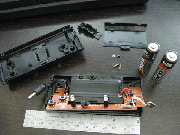
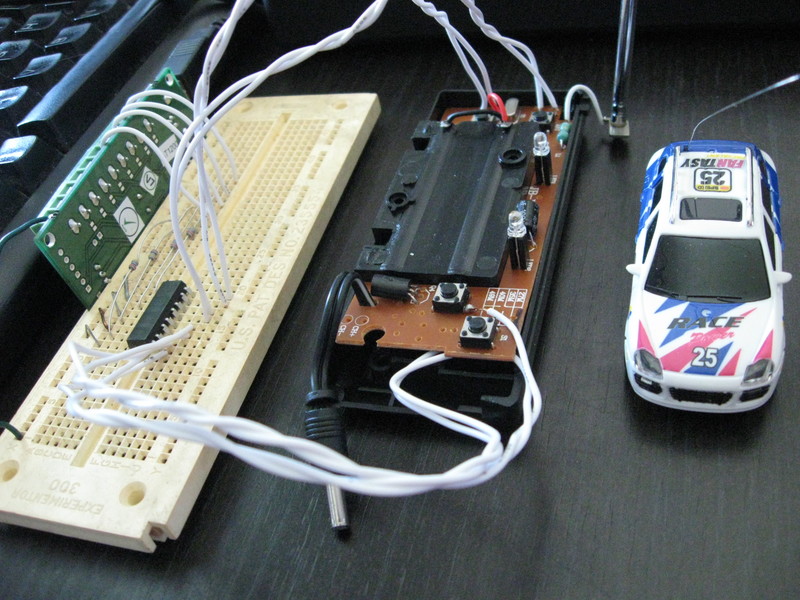
RC Controller Hardware
Here is the Remote Control transmitter disassembled. The four buttons are what control forward, backward, left, and right. These are what need to be connected too. The antenna mount is hanging from the white wire. The momentary push button switches need to be connected between pairs of leads on the same side of the package. In the photo of the top, the buttons on the left need their connections going to the front leads (the ones visible). The buttons are oriented 90 degrees differently on the right side. Some of the connections were easy to do from the top and some were easier to get at from the bottom. It doesn’t matter how you do it (or I got lucky and avoided hooking up to an extraneous terminal).

Control API
The API will be considered from the perspective of the driver agent. The driver’s commands will be output and the position data will be input.
Input
Ideally, the input would include:
-
X,Y position of the centroid of the car
-
Should be converted to mm
-
-
angular orientation of the car
-
0 is X+
-
90 is Y+
-
radians if that’s better
-
The track layout will be known in advance and is static for the run.
Output
-
GPIO 0 = Back
-
GPIO 1 = Forward
-
GPIO 2 = Left
-
GPIO 3 = Right
The driver agent can specify the following actions.
-
0 0 - Stop/coast 0000
-
set 1 - forward straight 0100
-
set 1, set 2 - forward left 0110
-
set 1, set 3 - forward right 0101
-
set 0 - backward straight 1000
-
set 0, set 2 - backward left 1010
-
set 0, set 3 - backward right 1001
Programming GPIO
To use C to write the output to the RC controller, just write to the port. Here is a useful example program that clears all of the GPIO pins.
#include <stdio.h>
int main (int argc, char *argv[]) {
    FILE *fd;
    fd = fopen("/dev/ttyACM0", "w");
    if (fd==NULL) {
        perror("Could not open /dev/ttyACM0. Maybe you need sudo?\n"); return 1;
        }
    int i; for (i=0;i<8;i++) {
        int n = fprintf(fd, "gpio clear %d\n\r",i);
        if (n < 0) perror("Output failed!\n");
        }
    fclose(fd); return 0;
    }
Complete Actuation Example
Here is a C program (and launcher) which will monitor the Linux keyboard events and set the correct GPIO output states. This maps the ASDW (or arrow) keys onto the correct GPIO pins to effectively manually drive the car with a keyboard control.
#!/bin/bash
GPIODEV="/dev/input/by-path/pci-0000:00:12.2-usb-0:1.3:1.0-event-kbd"
echo "Press 'Esc' followed by 'Ctrl-c' to quit."
stty -echo
sudo ./manual ${GPIODEV} &
cat > /dev/null
stty echo
/*   Chris X Edwards - Manual Mini Car Driver - 2014-07-24   *
 *   Compile with: gcc -o manual manual.c                    */
#include <stdio.h>
#include <fcntl.h>
#include <linux/input.h>

int main (int argc, char *argv[]) {
    int gpio[4]= {0,0,0,0};
    int i, kbfd; /* File id int for keyboard events. */
    FILE *gpiofd; /* File descriptor for the gpio device */
    struct input_event ev[64];
    if (argc != 2) {
        fprintf(stderr, "usage: %s event-device (/dev/input/eventX)\n", argv[0]);
        return 1;
        }
    if ((kbfd = open(argv[1], O_RDONLY)) < 0) { perror("Couldn't open input device");
        return 1;
        }
    gpiofd = fopen("/dev/ttyACM0", "w");
    if (gpiofd==NULL) {
        perror("Could not open GPIO device. Maybe you're not root?\n"); return 1;
        }
    while (1) {
        size_t rb = read(kbfd, ev, sizeof(ev));
        if (rb < (int) sizeof(struct input_event)) {
            perror("short read");
            return 1;
            }
        for (i = 0; i < (int) (rb / sizeof(struct input_event)); i++) {
            if (EV_KEY == ev[i].type) {
                if (ev[i].value == 1) { /* 1=KEY_PRESS, 2=KEY_KEEPING_PRESSED */
                    switch (ev[i].code) {
                        case 1 : printf("Stopping. Press Ctrl-c to quit.\n"); return 0;
                        case 108: case 31: gpio[0]= 1; gpio[1]= 0; break; /* back */
                        case 103: case 17: gpio[1]= 1; gpio[0]= 0; break; /* forward */
                        case 105: case 30: gpio[2]= 1; gpio[3]= 0; break; /* left */
                        case 106: case 32: gpio[3]= 1; gpio[2]= 0; break; /* right */
                        }
                    }
                else {
                    if (ev[i].value == 0) { /* 0=KEY_RELEASE */
                        switch (ev[i].code) {
                            case 108: case 31: gpio[0]= 0; break; /* !back */
                            case 103: case 17: gpio[1]= 0; break; /* !forward */
                            case 105: case 30: gpio[2]= 0; break; /* !left */
                            case 106: case 32: gpio[3]= 0; break; /* !right */
                            }
                        }
                    }
                }
            }
            for (i=0; i<4; i++) {
                if (gpio[i]) {
                    int n = fprintf(gpiofd, "gpio set %d\n\r",i);
                    if (n < 0) perror("Output failed!\n");
                    }
                else {
                    int n = fprintf(gpiofd, "gpio clear %d\n\r",i);
                    if (n < 0) perror("Output failed!\n");
                    }
                }
        }
    fclose(gpiofd); return 0;
    }
Modified Interface
A second interface could calculate virtual sensor readings (like the SCR feedback) from the track layout and the position but that’s not especially compelling at this time.
Driver AI
With the physical system in place the bot programming will be much like it is for the Simulated Car Racing competitions.
See my SnakeOil page for my previous work in this area.
![]()