Sometimes I get a wild idea in my head - actually, I specialize in that. This week’s wild idea was that I need to learn more about oscilloscopes. I’ve been working on my electrical engineering notes and my newly appreciated ignorance about oscilloscopes was irking me.
Looking online for interesting resources that could educate me about the topic, I wondered if electrical engineers ever acquire electronics equipment the most honorable way possible: by making it themselves. I always found that the best machinists had a lot of tooling that they had machined themselves.
That led me to discover the kuman DSO 138 DIY Oscilloscope Kit Opening Source 2.4" TFT 1MSPS Digital Oscilloscope Kit with DIY Parts & Probe, Handheld Pocket Sized 13803K, SMD pre-soldered. Wow!!!
That sounded awesome. I had to give it a try and I ordered one. My expectations were reasonable. I figured it had about even chances to (A) be defective or missing a part, (B) fail because of some ineptitude on my part, or (C) actually work. At the very least, I expected that I would get some soldering practice. When it arrived, I set to practicing!
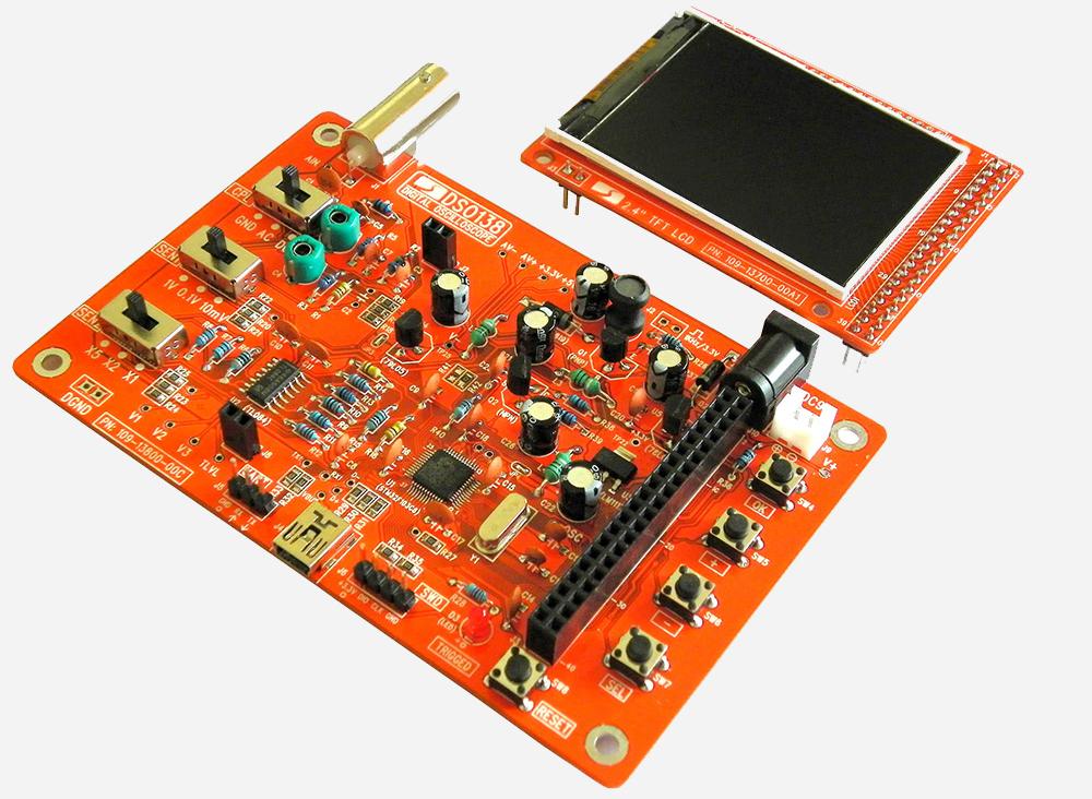
According to the instructions, a completed unit should look like this.
However what actually showed up was this.
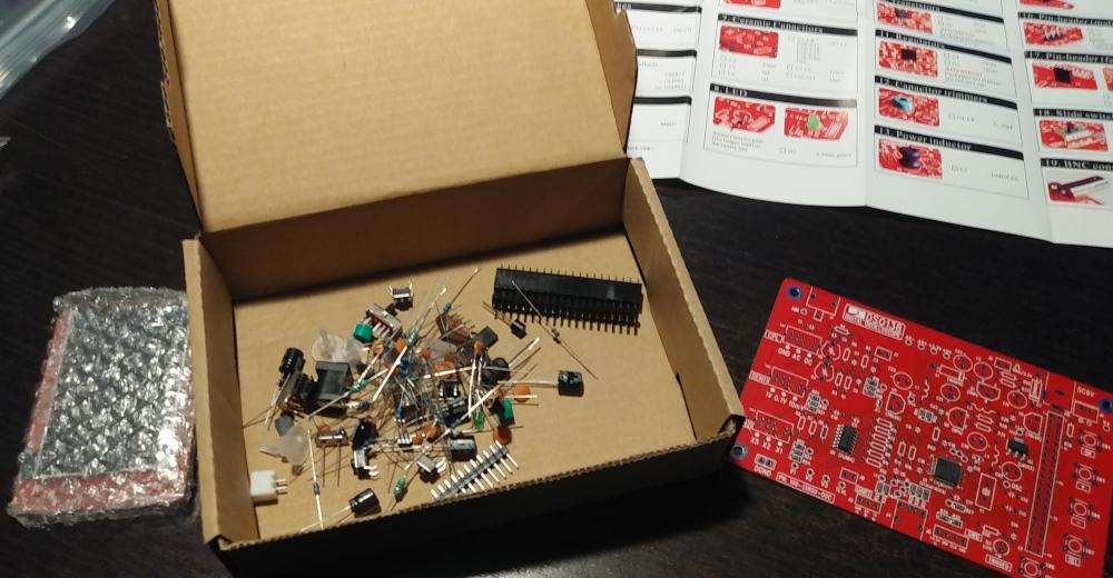
Gulp! Some extreme attention to detail was required to make sure all the values were thoroughly checked and all components sorted. I actually used all of the functions on my multimeter for this project, several for the first time. Just knowing how to test transistors with my meter was worth $22.
Finally, after a lot meticulous work, I was ready to power it up. I did the preliminary assembly power checks and they came out good! Wow! I attached the display and powered it up and it was… iffy. After playing with it, I had seen it boot properly and sort of work and I had also seen it act completely rubbish. Hmm.
Carefully studying every connection, I found some dodgy soldering. I actually did all the resistors and capacitors with my beloved 25 year old gas powered soldering iron. Unfortunately, its tip was so worn that it wasn’t doing a great job. After fixing up some of that with a newer iron I discovered a single lead that I had missed — no solder at all. Oops. I fixed that and when I subsequently booted it, it came up fine and worked flawlessly! It was a euphoric feeling to pull off a correct execution and be so damn lucky.
Ok, cool. I built an oscilloscope. Uh, what now? What do I do with it? After playing around with it I got the very good idea to hook it up to a guitar. I just put the probes on one end of a 1/4" patch cable plug — other end on the guitar. Then I was able to see the sound waves. Amazing! So cool.
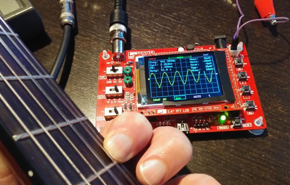
In this image you can see I’m holding down the 5th fret (note dot) on
the E string which is an A (E - open, F - 1st fret, F# - 2nd, G - 3rd,
G# - 4th, A - 5th). That A is actually the
A440 pitch
standard described in ISO
16:1975 used to standardize all of music to a certain pitch.
Obviously if my guitar is in tune, the frequency of the sound wave
should be 440. And you can see on the top left that it is reading
Freq: 441.707Hz. You can also get a sense for the amount of voltage
produced by a guitar pickup. Actually I have an unusual
Yamaha
SLG Series and I have no idea how its invisible magic pickups work — with nylon strings no less. But we can see that the voltage while this
note rings goes between 16mV and -20mV, for (presumably) the Vpp (peak
to peak?) of 36mV.
Although this would have been even more fun back when I had enviable eyesight, I’m still absolutely delighted with this project. I have learned a lot about a lot of different topics and have added a very powerful tool to my collection. What a cool little device!
UPDATE 2020-09-20
Having enjoyed that, I looked around for more such fun and found this signal generator kit. For only $12, I got to build this thing.

As you can see it does a nice job of giving my oscilloscope something to do. I think one of the main use cases for a signal generator (conceptually) is comparing this oscilloscope with a fancier, more accurate (?) one. But for now I’m just content that it generates square waves, sine waves, and the triangle waveform shown.